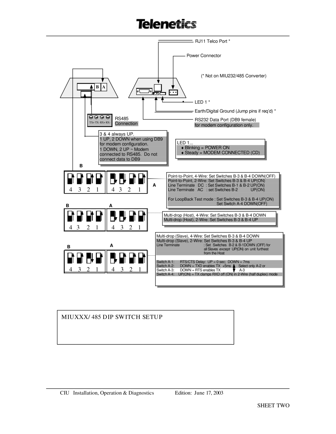
B A |
RJ11 Telco Port *
Power Connector
(* Not on MIU232/485 Converter)
| RS485 |
TX+ TX- RX+ RX- | Connection |
|
3 & 4 always UP.
1 UP, 2 DOWN when using DB9 for modem configuration.
1 DOWN, 2 UP ~ Modem connected to RS485. Do not connect data to DB9
B
LED 1 *
Earth/Digital Ground (Jump pins if req’d) *
RS232 Data Port (DB9 female) for modem configuration only.
LED 1...
♦Blinking = POWER ON
♦Steady = MODEM CONNECTED (CD)
4 | 3 | 2 | 1 | 4 | 3 | 2 | 1 |
B |
|
|
| A |
|
|
|
4 | 3 | 2 | 1 | 4 | 3 | 2 | 1 |
B |
|
|
| A |
|
|
|
4 | 3 | 2 | 1 | 4 | 3 | 2 | 1 |
ALine Terminate DC : Set Switches
Line Terminate AC : set Switches | UP(ON) |
For LoopBack Test mode : Set Switches | |
Set Switch | |
Line Terminate | : Set Switches | |||
| all Slaves except | UP(ON) on unit furthest | ||
| from the Host |
|
|
|
|
|
|
| |
Switch | RTS/CTS Delay: UP = 0 sec; DOWN = 7ms | |||
Switch | DOWN = TXD enables TX +5ms |
|
| Select only |
Switch | DOWN = RTS enables TX |
|
| |
Switch
MIUXXX/485 DIP SWITCH SETUP
CIU Installation, Operation & Diagnostics | Edition: June 17, 2003 |