1 |
1 General
The application note is intended to show how to assemble the cable and setup the hardware of the IP223 for channel change and FleetSync applications using Kenwood radio.
2 Setup
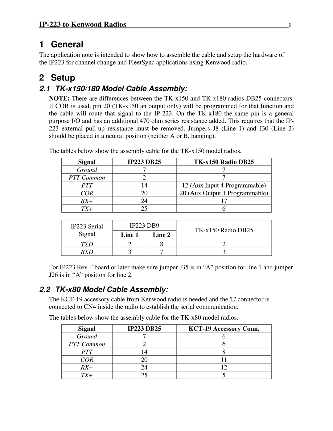
2.1 TK-x150/180 Model Cable Assembly:
NOTE: There are differences between the
The tables below show the assembly cable for the
Signal | IP223 DB25 |
| ||
Ground |
| 7 |
| 7 |
PTT Common |
| 2 |
| 7 |
PTT |
| 14 | 12 (Aux Input 4 Programmable) | |
COR |
| 20 | 20 (Aux Output 1 Programmable) | |
RX+ |
| 24 | 17 | |
TX+ |
| 25 | 6 | |
|
|
|
| |
IP223 Serial | IP223 DB9 | |||
Signal |
|
|
| |
Line 1 |
| Line 2 | ||
|
| |||
TXD | 2 |
| 8 | 2 |
RXD | 3 |
| 7 | 3 |
For IP223 Rev F board or later make sure jumper J35 is in “A” position for line 1 and jumper J26 is in “A” position for line 2.
2.2 TK-x80 Model Cable Assembly:
The
The tables below show the assembly cable for the
Signal | IP223 DB25 | |
Ground | 7 | 6 |
PTT Common | 2 | 6 |
PTT | 14 | 8 |
COR | 20 | 11 |
RX+ | 24 | 12 |
TX+ | 25 | 5 |