ASSEMBLY
Figure 7 HANDLE ASSEMBLY
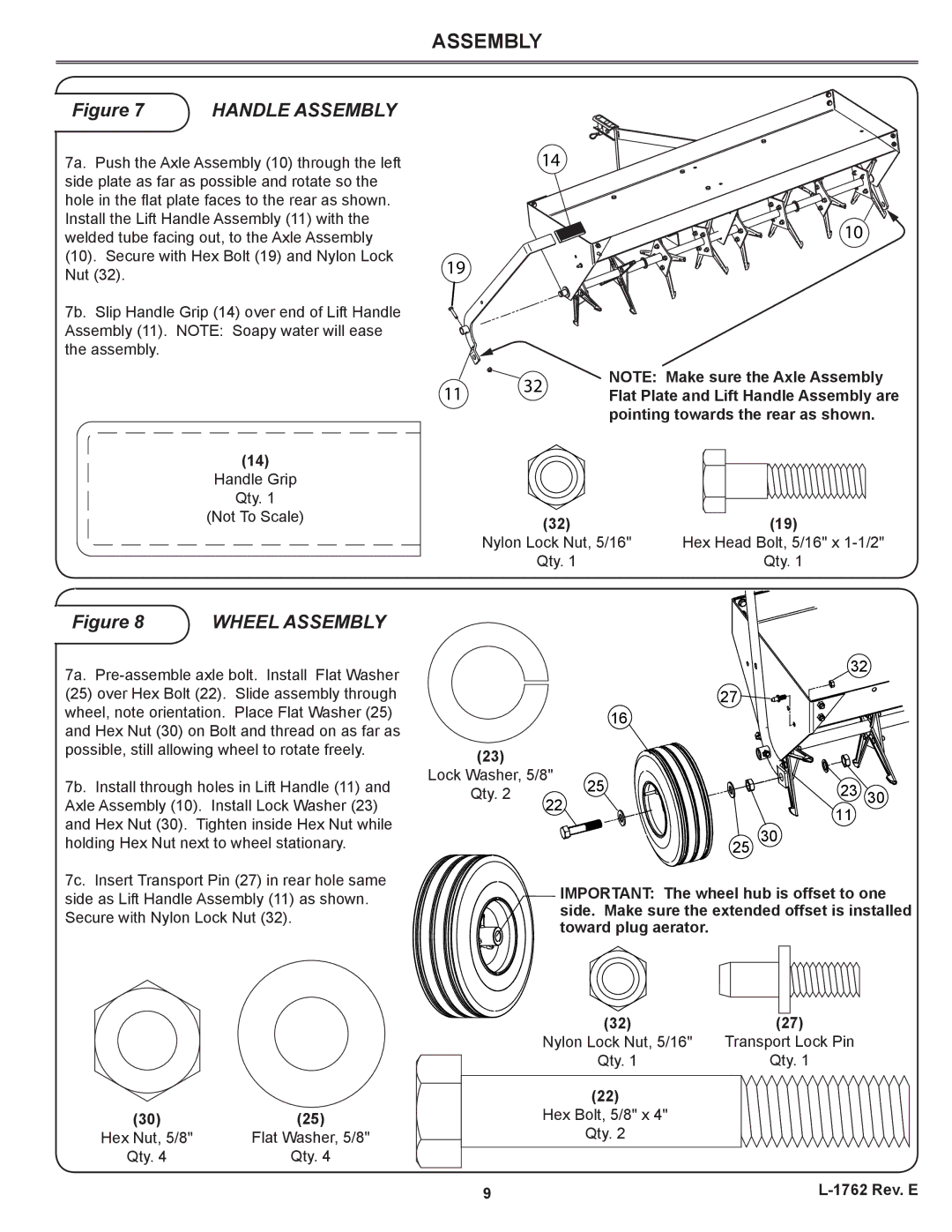
7a. Push the Axle Assembly (10) through the left side plate as far as possible and rotate so the hole in the flat plate faces to the rear as shown. Install the Lift Handle Assembly (11) with the welded tube facing out, to the Axle Assembly
(10). Secure with Hex Bolt (19) and Nylon Lock Nut (32).
7b. Slip Handle Grip (14) over end of Lift Handle Assembly (11). NOTE: Soapy water will ease the assembly.
(14)
Handle Grip
Qty. 1
14
19![]()
11 32
10
NOTE: Make sure the Axle Assembly Flat Plate and Lift Handle Assembly are pointing towards the rear as shown.
(Not To Scale)
(32) | (19) |
Nylon Lock Nut, 5/16" | Hex Head Bolt, 5/16" x |
Qty. 1 | Qty. 1 |
Figure 8 | WHEEL ASSEMBLY |
7a.
(25)over Hex Bolt (22). Slide assembly through wheel, note orientation. Place Flat Washer (25) and Hex Nut (30) on Bolt and thread on as far as possible, still allowing wheel to rotate freely.
7b. Install through holes in Lift Handle (11) and Axle Assembly (10). Install Lock Washer (23) and Hex Nut (30). Tighten inside Hex Nut while holding Hex Nut next to wheel stationary.
16
(23) |
|
| |
Lock Washer, 5/8" | 25 | ||
Qty. 2 | 22 | ||
| |||
|
| ||
32
27 ![]()
![]()
![]()
![]()
![]()
![]()
![]()
![]()
23 30 ![]()
![]()
![]()
11
25 30
7c. Insert Transport Pin (27) in rear hole same side as Lift Handle Assembly (11) as shown. Secure with Nylon Lock Nut (32).
![]()
![]()
![]()
![]()
![]()
![]()
![]()
![]()
![]()
![]()
![]()
![]()
![]()
![]()
![]()
![]()
![]()
![]()
![]()
![]()
![]()
![]()
![]()
![]()
![]()
![]()
![]()
![]()
![]()
![]() IMPORTANT: The wheel hub is offset to one
IMPORTANT: The wheel hub is offset to one
side. Make sure the extended offset is installed toward plug aerator.
(30) | (25) |
Hex Nut, 5/8" | Flat Washer, 5/8" |
Qty. 4 | Qty. 4 |
(32) | (27) |
Nylon Lock Nut, 5/16" | Transport Lock Pin |
Qty. 1 | Qty. 1 |
(22) |
|
Hex Bolt, 5/8" x 4" |
|
Qty. 2 |
|
9 |