System Configuration
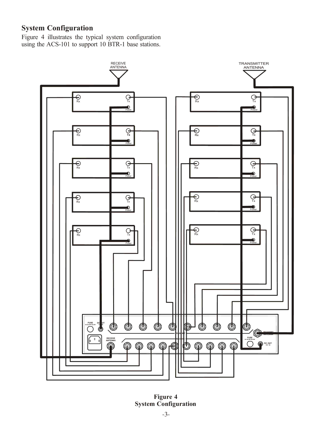
Figure 4 illustrates the typical system configuration
using the ACS-101 to support 10 BTR-1 base stations.
| RECEIVE |
|
| ANTENNA |
|
Rx | Tx | Rx |
| Power |
|
Rx | Tx | Rx |
| Power |
|
Rx | Tx | Rx |
| Power |
|
Rx | Tx | Rx |
| Power |
|
Rx | Tx | Rx |
| Power |
|
FUSE | DC OUT |
|
5A SLOW BLOW | 12V 5A |
|
|
| TRANSMIT |
| RECEIVE | RECEIVE |
| ANTENNA |
|
Figure 4
System Configuration
TRANSMITTER
ANTENNA
Tx
Power
Tx
Power
Tx
Power
Tx
Power
Tx
Power
TRANSMIT
ANTENNA
FUSE
5A SLOW BLOW
DC OUT
12V 5A