Connections, Fuses and Indicators | 1 | |||
|
|
|
|
|
| RadioComTM | |||
| by Telex | UHF Antenna Splitter/Combiner | ||
|
|
|
|
|
|
| POWER - GREEN | ||
|
| OVERHEAT - RED | ||
|
|
|
|
|
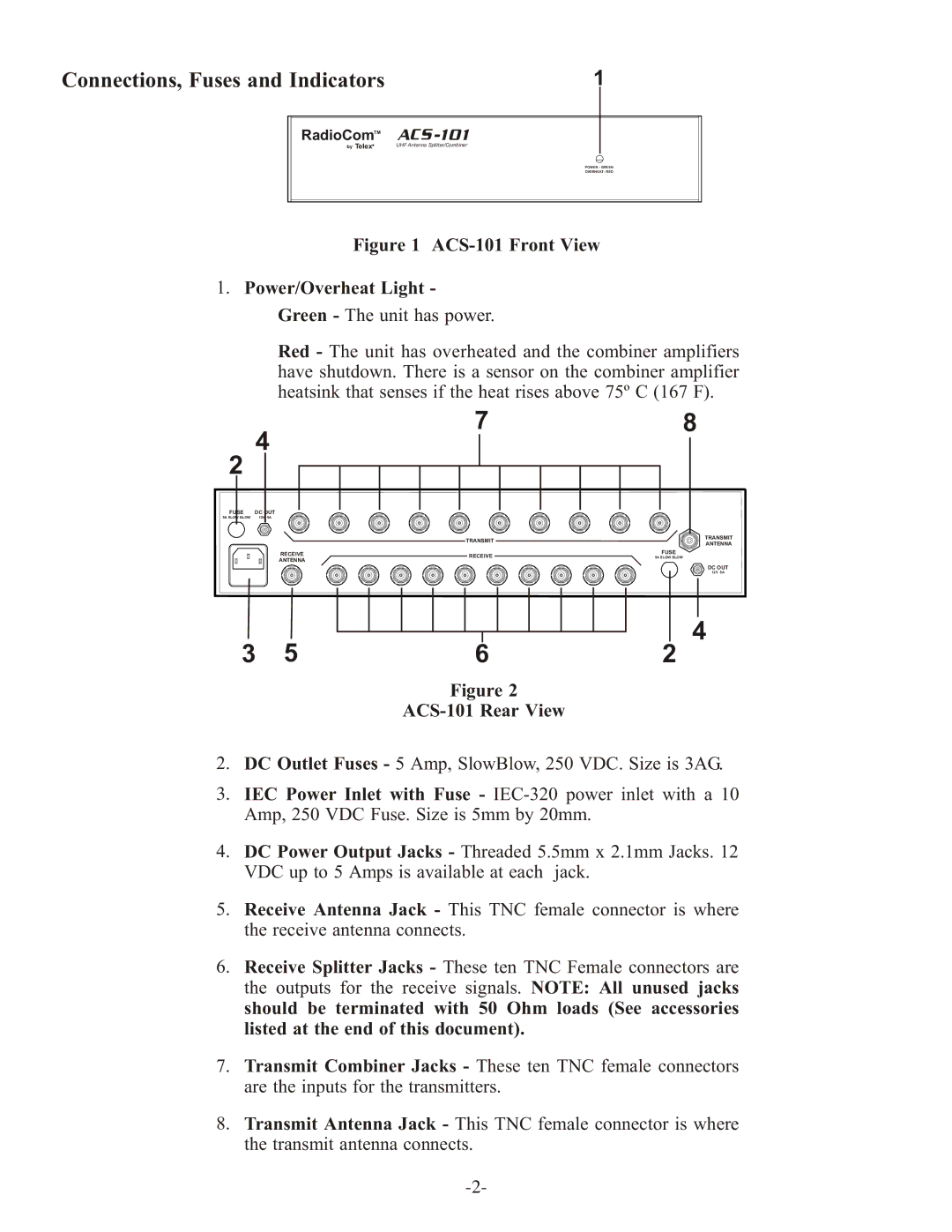
Figure 1 ACS-101 Front View
1.Power/Overheat Light - Green - The unit has power.
Red - The unit has overheated and the combiner amplifiers have shutdown. There is a sensor on the combiner amplifier heatsink that senses if the heat rises above 75º C (167 F).
78
4
2
FUSE | DC OUT | ||||
5A SLOW BLOW | 12V 5A | ||||
|
|
|
|
|
|
| TRANSMIT |
|
RECEIVE | RECEIVE | FUSE |
5A SLOW BLOW | ||
ANTENNA |
|
|
TRANSMIT ANTENNA
DC OUT
12V 5A
4
3 | 5 | 6 | 2 |
Figure 2
ACS-101 Rear View
2.DC Outlet Fuses - 5 Amp, SlowBlow, 250 VDC. Size is 3AG.
3.IEC Power Inlet with Fuse -
4.DC Power Output Jacks - Threaded 5.5mm x 2.1mm Jacks. 12 VDC up to 5 Amps is available at each jack.
5.Receive Antenna Jack - This TNC female connector is where the receive antenna connects.
6.Receive Splitter Jacks - These ten TNC Female connectors are the outputs for the receive signals. NOTE: All unused jacks should be terminated with 50 Ohm loads (See accessories listed at the end of this document).
7.Transmit Combiner Jacks - These ten TNC female connectors are the inputs for the transmitters.
8.Transmit Antenna Jack - This TNC female connector is where the transmit antenna connects.