Antenna Placement
for Optimum Range and Rack Mounting
For maximum range and when rack mounting, the antennas must be remotely located.
The
Antennas should be placed in a location with a clear “signal path” to the beltpacks. This “path” should be as short and free of obstructions as possible. Ob- structions, such as walls ceilings, and metal objects, will reduce range and performance.
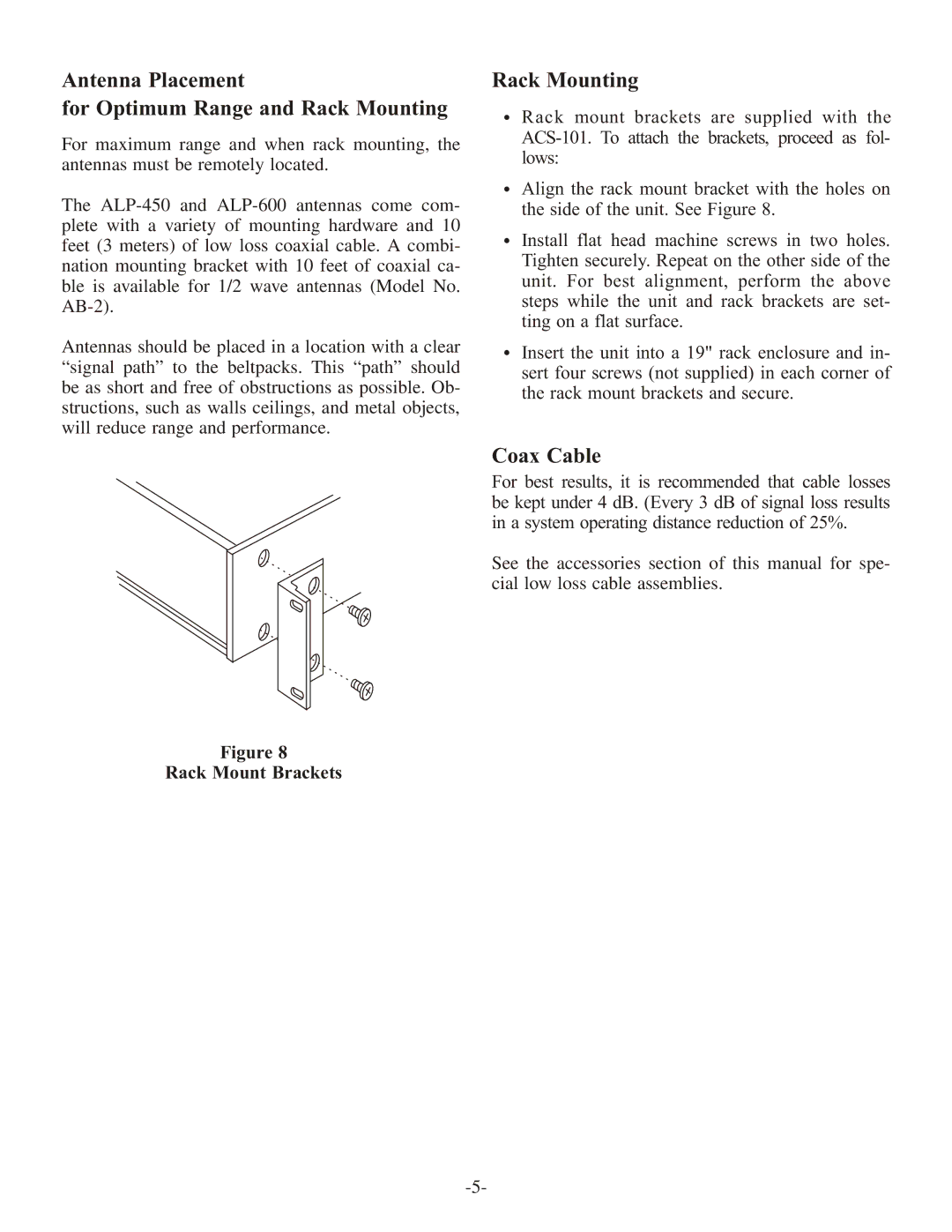
Figure 8
Rack Mount Brackets
Rack Mounting
·Rack mount brackets are supplied with the
lows:
·Align the rack mount bracket with the holes on the side of the unit. See Figure 8.
·Install flat head machine screws in two holes. Tighten securely. Repeat on the other side of the
unit. For best alignment, perform the above steps while the unit and rack brackets are set- ting on a flat surface.
·Insert the unit into a 19" rack enclosure and in- sert four screws (not supplied) in each corner of
the rack mount brackets and secure.
Coax Cable
For best results, it is recommended that cable losses be kept under 4 dB. (Every 3 dB of signal loss results in a system operating distance reduction of 25%.
See the accessories section of this manual for spe- cial low loss cable assemblies.