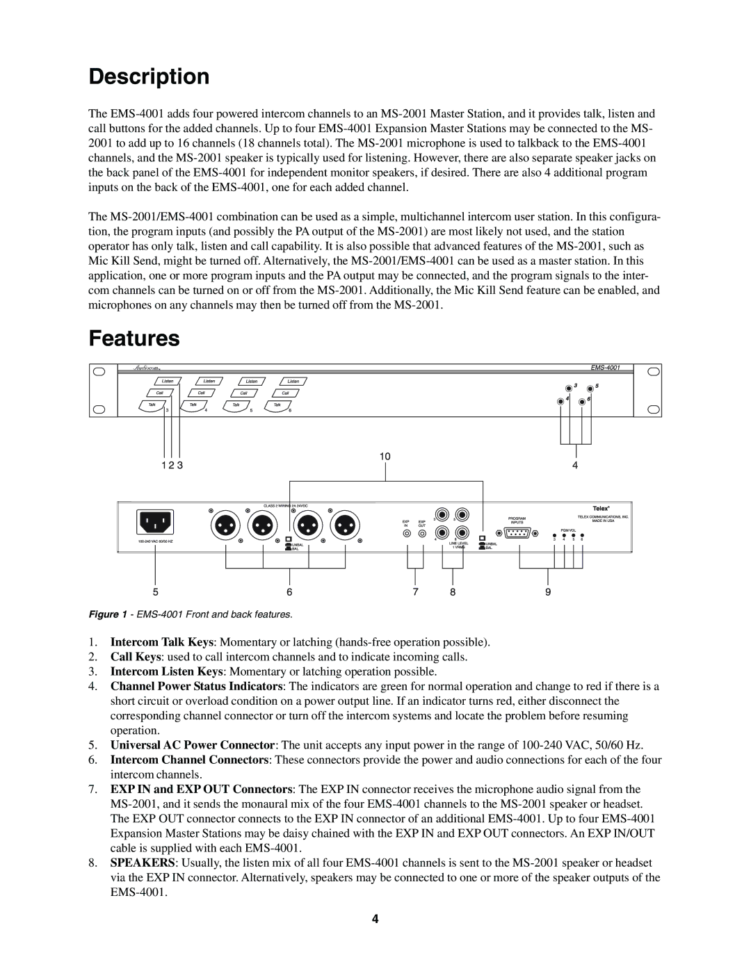
EMS-4001 specifications
The Telex EMS-4001 is a prominent digital intercom system renowned for its exceptional audio quality and user-friendly interface. Geared toward professional audio environments such as broadcast studios, theater productions, and large event venues, the EMS-4001 offers reliable communication solutions that enhance operational efficiency.One of the standout features of the EMS-4001 is its user-defined channel configurations. This allows operators to customize the intercom channels according to specific needs and workflows, accommodating both simple and complex communication setups. The system supports multiple channels simultaneously, ensuring that all team members can communicate without interference, which is crucial in high-pressure environments.
The EMS-4001 utilizes advanced digital signal processing technology, which enhances sound clarity and minimizes latency. With superior audio quality, users can enjoy crystal-clear communication, even in noisy settings. The digital transmission also provides resistance to electromagnetic interference, which is particularly important in broadcast or live event situations where electronic devices are abundant.
The intercom system is designed with versatility in mind. It features various connection options, including wired and wireless setups, allowing operators the flexibility to determine the best arrangement for their specific requirements. With options for belt-packs and desktop stations, the EMS-4001 is adaptable for use by different roles within a production team, from stage managers to sound engineers.
Another notable characteristic of the EMS-4001 is its robust build quality. Crafted to withstand the rigors of live events, the hardware is both durable and lightweight, making it suitable for quick deployment and transportation. This reliability ensures that users can depend on the system to perform consistently, minimizing downtime during critical moments.
Additionally, the EMS-4001 incorporates features such as programmable buttons and user-friendly visual displays, which streamline operation and facilitate quick access to essential functions. These aspects make it even easier for users to manage communications on the fly, contributing to a more efficient workflow during events.
In summary, the Telex EMS-4001 digital intercom system stands out for its customizable channel configurations, remarkable audio fidelity, versatile connectivity options, and solid construction. Its advanced technologies and thoughtful design make it an ideal choice for professionals seeking to optimize their communication capabilities in demanding audio environments.

