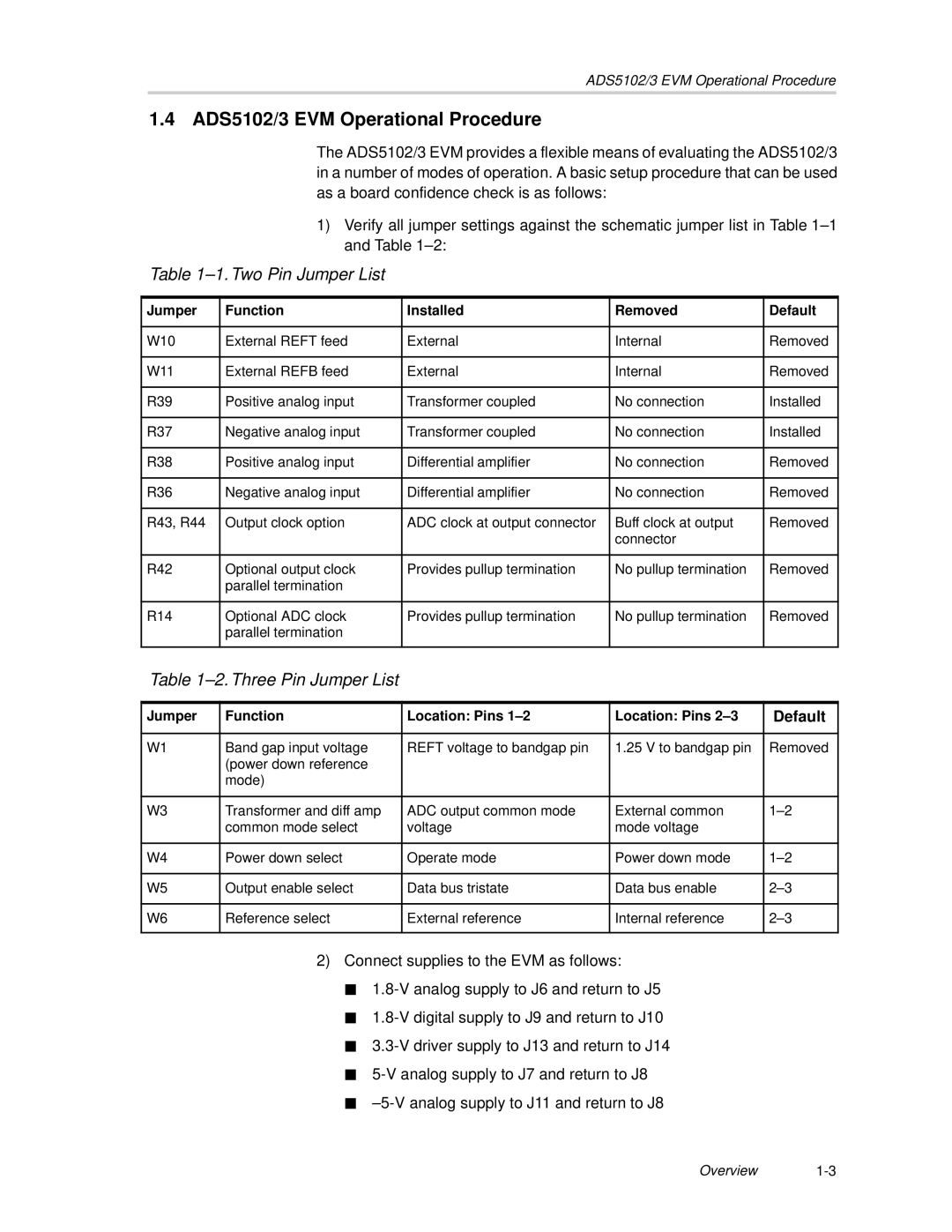
ADS5103 EVM, ADS5102 EVM specifications
Texas Instruments is known for its innovation in analog and embedded processing technologies, and the ADS5102 and ADS5103 Evaluation Modules (EVM) exemplify this legacy. These high-performance data converters are designed to meet the needs of a wide range of applications in industrial, medical, and communication systems.The ADS5102 and ADS5103 EVMs are equipped with high-speed analog-to-digital converters (ADCs) that boast impressive specifications. The ADS5102 features a 12-bit resolution, while the ADS5103 pushes boundaries further with 14-bit resolution, ensuring exceptional accuracy in signal conversion. Operating at a sampling rate of up to 250 MSPS, both modules enable the processing of high-frequency signals with minimal latency. This makes them ideal for applications that require real-time data acquisition and processing.
A standout feature of both EVMs is their Error Vector Magnitude (EVM) performance, which allows for low distortion and high linearity in signal processing. This characteristic is critical for applications such as communications, where signal integrity is paramount. The combination of high bit resolution and low EVM makes these devices a natural choice for advanced systems requiring clear and accurate signal representation.
Technology-wise, the EVMs utilize a high-speed deserializer for efficient transmission of data. This feature supports advanced communication protocols, enabling seamless integration with digital signal processors (DSPs) or FPGAs. The design includes flexible input options, allowing users to connect various analog sources and easily adapt the systems to different use cases.
The ADS5102 and ADS5103 EVMs also provide comprehensive software support, including TI’s high-performance software libraries. This enables users to quickly set up their evaluation environment and perform thorough testing and analysis. In addition, the modular design of the EVMs allows for easy upgrades and modifications, making them versatile tools for engineers.
In summary, the Texas Instruments ADS5102 and ADS5103 EVMs are powerful evaluation tools for high-speed, high-resolution data conversion. With their exceptional sampling rates, low distortion, and user-friendly design, they serve as vital components in the development of advanced signal processing systems across various industries. These EVMs not only demonstrate Texas Instruments' commitment to quality and innovation but also provide engineers with the essential tools needed to drive their designs forward.
