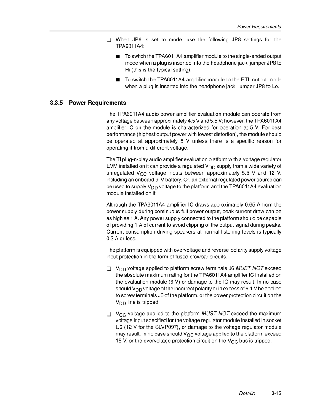
SLOU121 specifications
Texas Instruments SLOU121 is a comprehensive technical document that serves as a guide for the evaluation and implementation of various TI products. This document highlights the operational capabilities, design considerations, and practical applications of TI’s semiconductor solutions, with a focus on enabling engineers and designers to optimize their designs effectively.One of the main features of SLOU121 is its emphasis on performance. It provides detailed specifications and operational data that help users understand the key parameters of TI products, such as voltage levels, current ratings, and thermal characteristics. This information is crucial for engineers as they design circuits that require precision and reliability.
The document also covers various technologies that Texas Instruments employs in its semiconductor solutions. These technologies include advanced CMOS processes, which enable high integration and low power consumption. Additionally, the use of innovative materials and structures enhances the performance and efficiency of the components, thereby providing manufacturers with the tools they need to create cutting-edge electronics.
Another important characteristic of SLOU121 is its user-friendly layout and structure. Information is organized in a manner that allows for quick referencing, which is essential for busy engineers who need to find specific data efficiently. The inclusion of diagrams, graphs, and tables further aids in visualizing the performance metrics and operational limits of the devices discussed.
Moreover, SLOU121 delves into specific applications where TI products excel. These applications range from automotive systems to industrial automation and consumer electronics. The guide also addresses compatibility with industry standards and protocols, which is vital for integration into existing systems.
In addition to technical specifications, the document provides guidance on practical implementation strategies. This includes best practices for layout design, thermal management, and component selection. By incorporating these recommendations, engineers can mitigate potential issues during the design phase and ensure that their final products meet or exceed performance expectations.
Overall, Texas Instruments SLOU121 is an essential resource that combines technical knowledge with practical advice, helping engineers to leverage TI technologies for innovative product development. By providing a thorough understanding of features, technologies, and recommendations, SLOU121 equips designers with the necessary tools to create high-performance electronic solutions.
