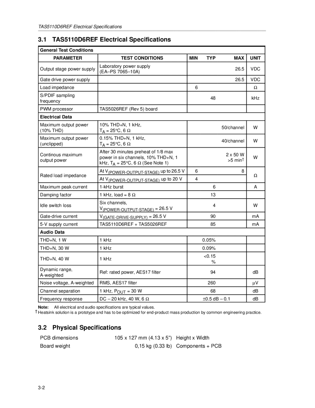
TAS5110D6REF specifications
The Texas Instruments TAS5110D6REF is a high-performance audio amplifier that is designed to integrate seamlessly into various audio applications, including home theater systems, professional audio devices, and consumer electronic products. As a representative of Texas Instruments' commitment to innovation and quality, the TAS5110D6REF offers a robust set of features, technologies, and characteristics that elevate it to the forefront of the audio amplifier market.One of the main features of the TAS5110D6REF is its advanced digital power management technology, which allows for high efficiency and low heat generation. This ensures that the audio amplifier can deliver powerful performance without compromising on energy efficiency or thermal stability. The amplifier supports a wide range of power supply voltages, making it adaptable to various use cases.
The TAS5110D6REF supports a variety of audio formats, including Class D amplification, which is known for its high fidelity and the ability to drive high current loads. This technology allows the power amplifier to produce audio output with minimal distortion while maintaining excellent sound quality. Furthermore, the Class D architecture enables the design of compact audio solutions.
Another notable characteristic of the TAS5110D6REF is its high output power capability, which allows it to drive large speakers with ease. The amplifier boasts an effective output of up to 200 watts per channel in stereo mode, providing an immersive listening experience even in larger environments.
In terms of compatibility, the TAS5110D6REF integrates easily with digital signal processing systems, enhancing sound quality through sophisticated algorithms for audio processing. It also features a variety of built-in protections, such as short-circuit and over-temperature protection, ensuring reliability and longevity in operation.
Additionally, the device offers advanced feedback loops, which contribute to maintaining sound integrity and minimizing signal loss during amplification. This feature is particularly important for ensuring that the original audio signal remains true to its source, making it an excellent choice for audiophiles and professional audio engineers alike.
Overall, the Texas Instruments TAS5110D6REF exemplifies cutting-edge audio amplification technology with its powerful output, energy-efficient operation, and high-performance characteristics. It is well-suited for a variety of applications, delivering high-quality sound reproduction that meets the demands of modern audio systems. With its combination of features and reliability, the TAS5110D6REF represents a significant advancement in the realm of audio amplification.

