TAS5121, TAS5508-5121K8EVM specifications
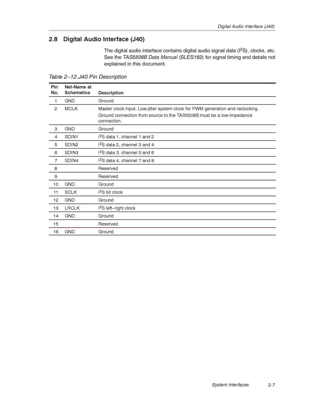
The Texas Instruments TAS5508-5121K8EVM is an advanced evaluation module that features the TAS5121 audio amplifier, designed to demonstrate the capabilities of TI’s innovative audio processing technology. This module is a key resource for engineers looking to explore high-performance audio systems and seamless integration into their product designs.One of the main features of the TAS5508-5121K8EVM is its ability to deliver high-quality digital audio amplification. The TAS5121 DAC (digital-to-analog converter) is featured prominently, supporting various digital audio interfaces such as I2S and PCM. This flexibility allows designers to interface the device with a wide range of digital signal processors and microcontrollers.
The TAS5121 incorporates a Class-D amplification architecture that significantly enhances audio performance while maintaining energy efficiency. Class-D amplifiers are known for their high efficiency, which translates to less heat generation and reduced power consumption compared to traditional linear amplifiers. This is particularly important in portable or battery-operated applications, where power management is crucial.
The evaluation module supports up to 128 watts of output power per channel, making it suitable for demanding audio applications such as home theater systems, professional audio equipment, and automotive sound systems. The TAS5121 is designed to operate at various load impedances, thus ensuring optimal sound quality across different speaker types.
The TAS5508-5121K8EVM also features integrated diagnostic capabilities that allow users to monitor the system's performance in real time. Built-in protections against over-temperature and over-current conditions contribute to the device’s robustness, making it suitable for long-term applications in diverse environments.
Moreover, the evaluation module supports seamless integration with TI’s PurePath™ platform, which enhances digital audio processing through advanced algorithms. These technologies promote superior sound reproduction, allowing users to take advantage of dynamic range control and equalization features.
In summary, the Texas Instruments TAS5508-5121K8EVM with the TAS5121 audio amplifier is an essential tool for audio engineers and designers. Its combination of digital audio processing, Class-D amplification, robust diagnostic features, and support for high output power make it a versatile solution for a range of high-performance audio applications. As technology continues to evolve, this evaluation module serves as a reliable foundation for developing next-generation audio products.
