Texas Instruments TPA6101A2 manual Quick Start List for Stand-Alone

Models: TPA6101A2

1 16
Download 16 pages 54.37 Kb
Page 14
Image 14
2.3 Quick Start List for Stand-Alone

Quick Start List for Stand-Alone

2.3 Quick Start List for Stand-Alone

Follow these steps to use the TPA6101A2 EVM
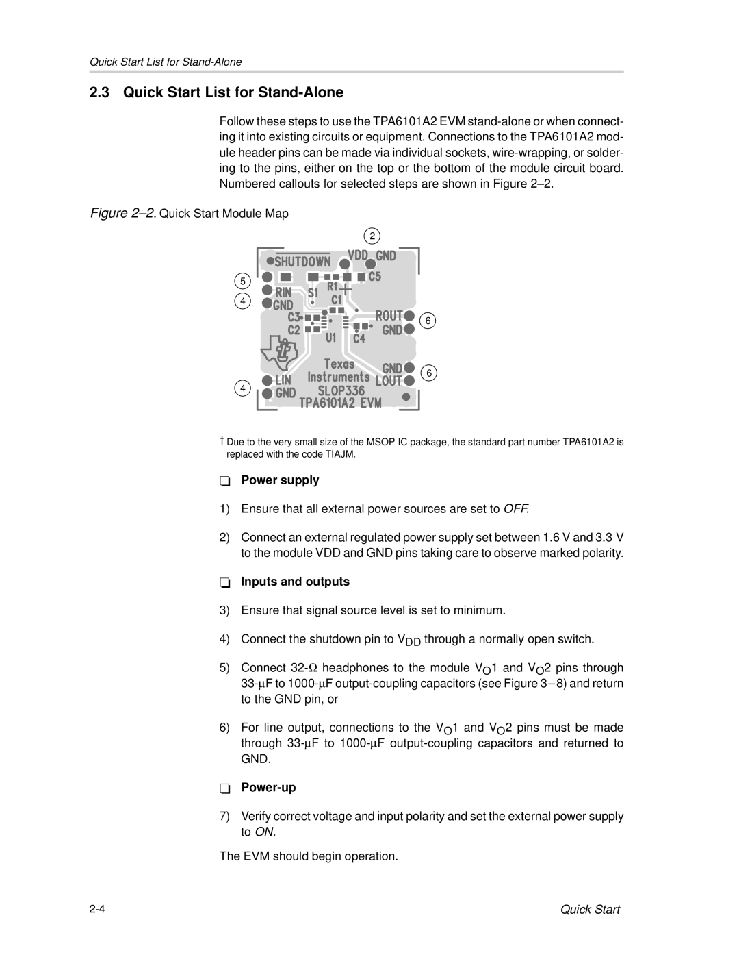
 stand-alone or when connect- ing it into existing circuits or equipment. Connections to the TPA6101A2 mod- ule header pins can be made via individual sockets, wire-wrapping, or solder- ing to the pins, either on the top or the bottom of the module circuit board. Numbered callouts for selected steps are shown in Figure 2–2.

Figure 2–2.Quick Start Module Map

2

5

4

6

6

4

Due to the very small size of the MSOP IC package, the standard part number TPA6101A2 is -replaced with the code TIAJM.

Power supply

1)Ensure that all external power sources are set to OFF.

2)Connect an external regulated power supply set between 1.6 V and 3.3 V -to the module VDD and GND pins taking care to observe marked polarity.

Inputs and outputs

3)Ensure that signal source level is set to minimum.

4)Connect the shutdown pin to VDD through a normally open switch.

5)Connect 32-headphones to the module VO1 and VO2 pins through 33-F to 1000-F output-coupling capacitors (see Figure 3 –8) and return

to the GND pin, or

6)For line output, connections to the VO1 and VO2 pins must be made through 33-F to 1000-F output-coupling capacitors and returned to

-GND.

Power-up

7)Verify correct voltage and input polarity and set the external power supply to ON.

The EVM should begin operation.

2-4

Quick Start

Page 14
Image 14
Texas Instruments TPA6101A2 manual Quick Start List for Stand-Alone