www.ti.com | Reference Design Assembly Drawing |
7Reference Design Assembly Drawing
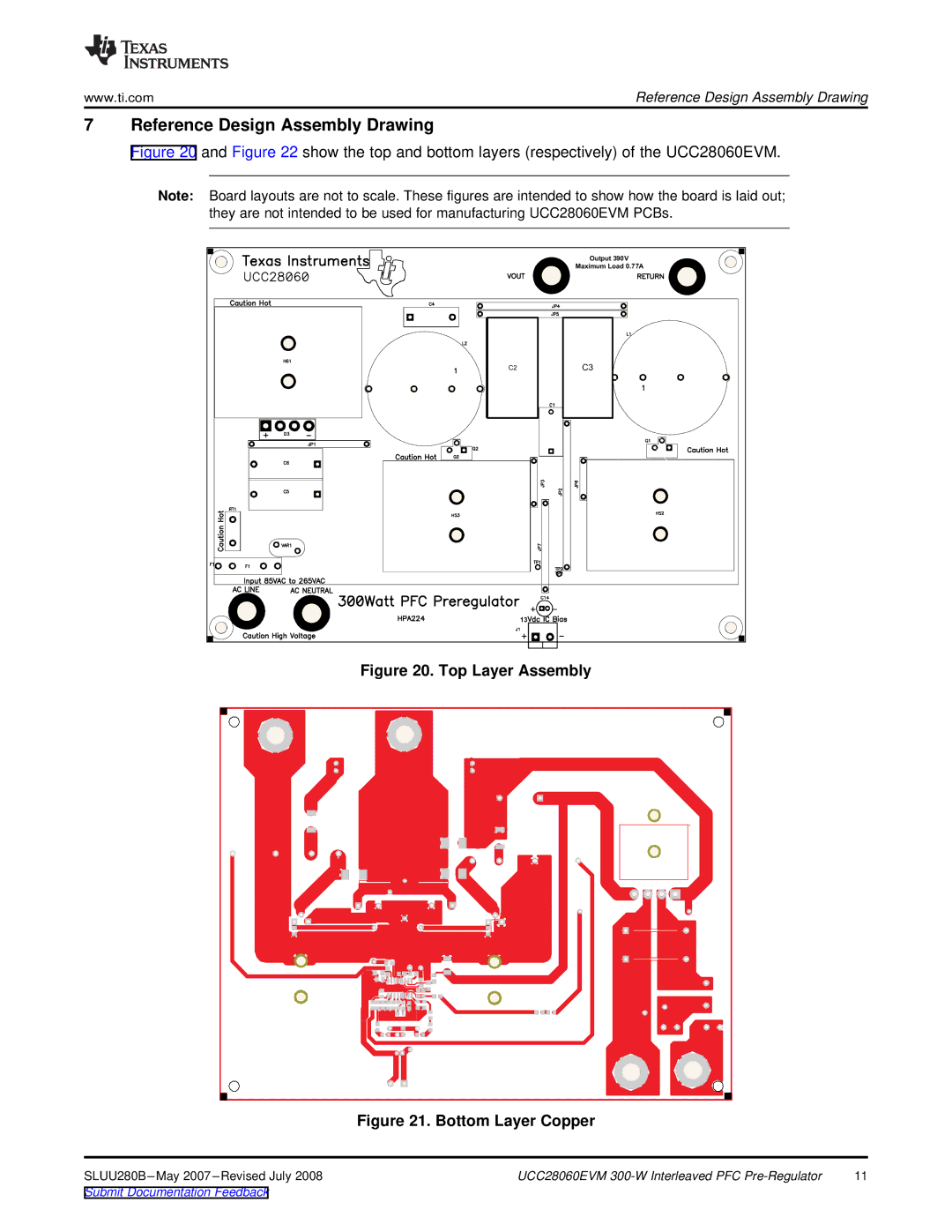
Figure 20 and Figure 22 show the top and bottom layers (respectively) of the UCC28060EVM.
Note: Board layouts are not to scale. These figures are intended to show how the board is laid out; they are not intended to be used for manufacturing UCC28060EVM PCBs.
Output 390V
Maximum Load 0.77A
C2 |
C3 |
13
Figure 20. Top Layer Assembly
Figure 21. Bottom Layer Copper
UCC28060EVM | 11 |
Submit Documentation Feedback