Test Setup and Power-Up/Power-Down Instructions | www.ti.com |
5 Test Setup and Power-Up/Power-Down Instructions
WARNING
There are high voltages present on the pre-regulator. It should only be handled by experienced power supply professionals. To evaluate this board as safely as possible, the following test configuration should be used:
∙Connect an isolation transformer between the source and unit
∙Attach a voltmeter and a resistive or electronic load to the unit output before supplying power to the EVM.
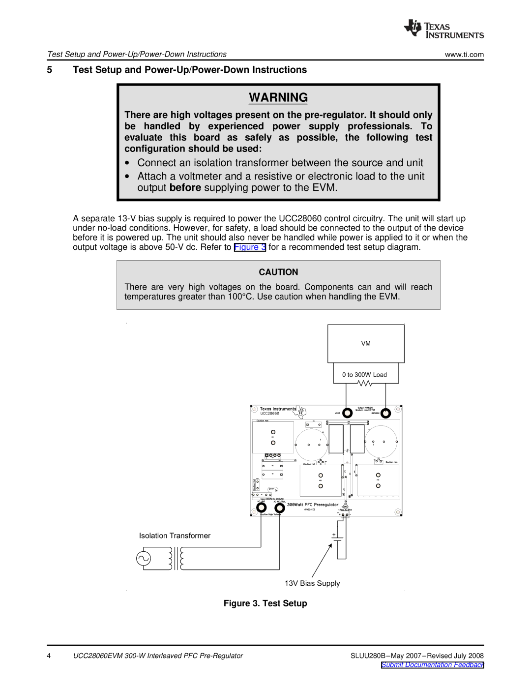
A separate 13-V bias supply is required to power the UCC28060 control circuitry. The unit will start up under no-load conditions. However, for safety, a load should be connected to the output of the device before it is powered up. The unit should also never be handled while power is applied to it or when the output voltage is above 50-V dc. Refer to Figure 3 for a recommended test setup diagram.
CAUTION
There are very high voltages on the board. Components can and will reach temperatures greater than 100°C. Use caution when handling the EVM.
VM
0 to 300W Load
13V Bias Supply
Figure 3. Test Setup
4 | UCC28060EVM 300-W Interleaved PFC Pre-Regulator | SLUU280B–May 2007–Revised July 2008 |
Submit Documentation Feedback