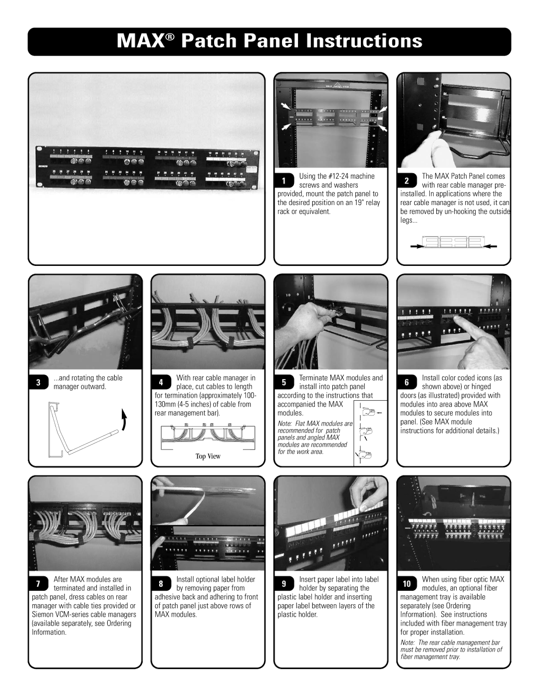
MAX® Patch Panel Instructions
3 | ...and rotating the cable | |
manager outward. | ||
|
With rear cable manager in
4 place, cut cables to length for termination (approximately 100- 130mm
Top View
Using the #12-24 machine
1 screws and washers provided, mount the patch panel to the desired position on an 19" relay rack or equivalent.
5 | Terminate MAX modules and | |
install into patch panel | ||
| ||
according to the instructions that | ||
accompanied the MAX | ||
modules. | ||
Note: Flat MAX modules are recommended for patch panels and angled MAX modules are recommended for the work area.
The MAX Patch Panel comes
2 with rear cable manager pre- installed. In applications where the rear cable manager is not used, it can be removed by
Install color coded icons (as
6 shown above) or hinged doors (as illustrated) provided with modules into area above MAX modules to secure modules into panel. (See MAX module instructions for additional details.)
7 | After MAX modules are | 8 | Install optional label holder | 9 | Insert paper label into label | |
terminated and installed in | by removing paper from | holder by separating the | ||||
|
|
| ||||
patch panel, dress cables on rear | adhesive back and adhering to front | plastic label holder and inserting | ||||
manager with cable ties provided or | of patch panel just above rows of | paper label between layers of the | ||||
Siemon | MAX modules. | plastic holder. | ||||
(available separately, see Ordering |
|
|
|
| ||
Information. |
|
|
|
| ||
When using fiber optic MAX
10 modules, an optional fiber management tray is available separately (see Ordering Information). See instructions included with fiber management tray for proper installation.
Note: The rear cable management bar must be removed prior to installation of fiber management tray.
