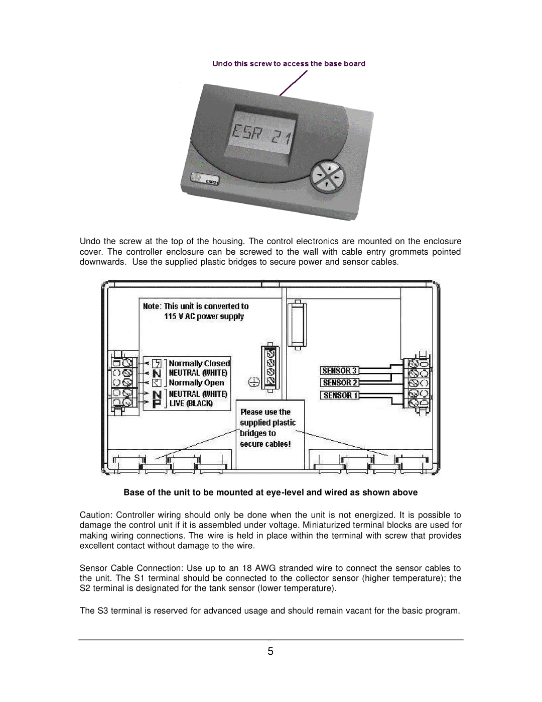
Undo the screw at the top of the housing. The control electronics are mounted on the enclosure cover. The controller enclosure can be screwed to the wall with cable entry grommets pointed downwards. Use the supplied plastic bridges to secure power and sensor cables.
Base of the unit to be mounted at
Caution: Controller wiring should only be done when the unit is not energized. It is possible to damage the control unit if it is assembled under voltage. Miniaturized terminal blocks are used for making wiring connections. The wire is held in place within the terminal with screw that provides excellent contact without damage to the wire.
Sensor Cable Connection: Use up to an 18 AWG stranded wire to connect the sensor cables to the unit. The S1 terminal should be connected to the collector sensor (higher temperature); the S2 terminal is designated for the tank sensor (lower temperature).
The S3 terminal is reserved for advanced usage and should remain vacant for the basic program.
5
