P ower Connections: A small blade screwdriver may be used to fasten miniaturized terminal block screws while the corresponding wire is inserted.
NOTE 1: Always disconnect the controller from power supply before opening the housing.
NOTE 2: The controller should be properly grounded. Flexible wires, 18/3 AWG (gauge/conductor) simplify connection to the terminals. The power terminal block will accommodate wire sizes to 14 AWG. All other connections should be secured and adequately tightened, as loose power connections will
NOTE 3: It is important that the specified output loads (245 Watts) are not exceeded. Where these loads expect to exceed, external relays must be used. It is good practice to install a switch to disconnect the controller and pump from power. Always keep power cables away from sensor cables and other low voltage signal cables.
NOTE 4: To protect against lightening damage, the system must be grounded according local regulation. Sensor failures due to the weather or electrostatic are mostly due to poor grounding.
BASIC OPERATION OF DIGITAL
DISPLAY
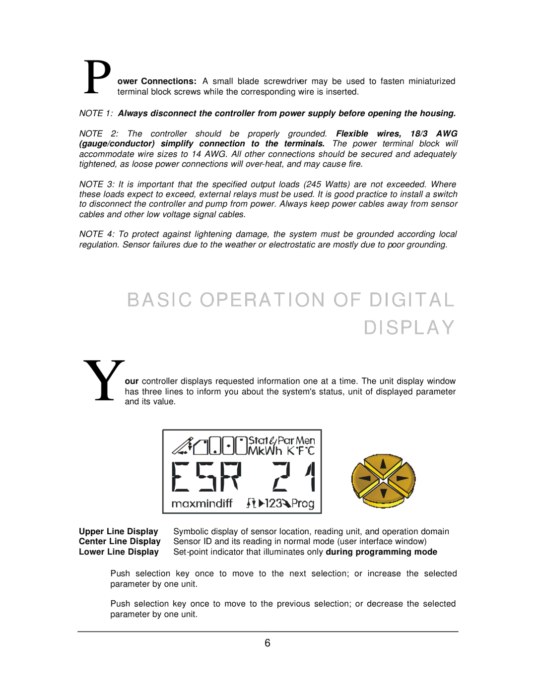
Your controller displays requested information one at a time. The unit display window has three lines to inform you about the system's status, unit of displayed parameter and its value.
Upper Line Display Symbolic display of sensor location, reading unit, and operation domain Center Line Display Sensor ID and its reading in normal mode (user interface window) Lower Line Display
ðPush selection key once to move to the next selection; or increase the selected parameter by one unit.
ïPush selection key once to move to the previous selection; or decrease the selected parameter by one unit.
6
