C-RM500
REMOTE CONTROLLER
The
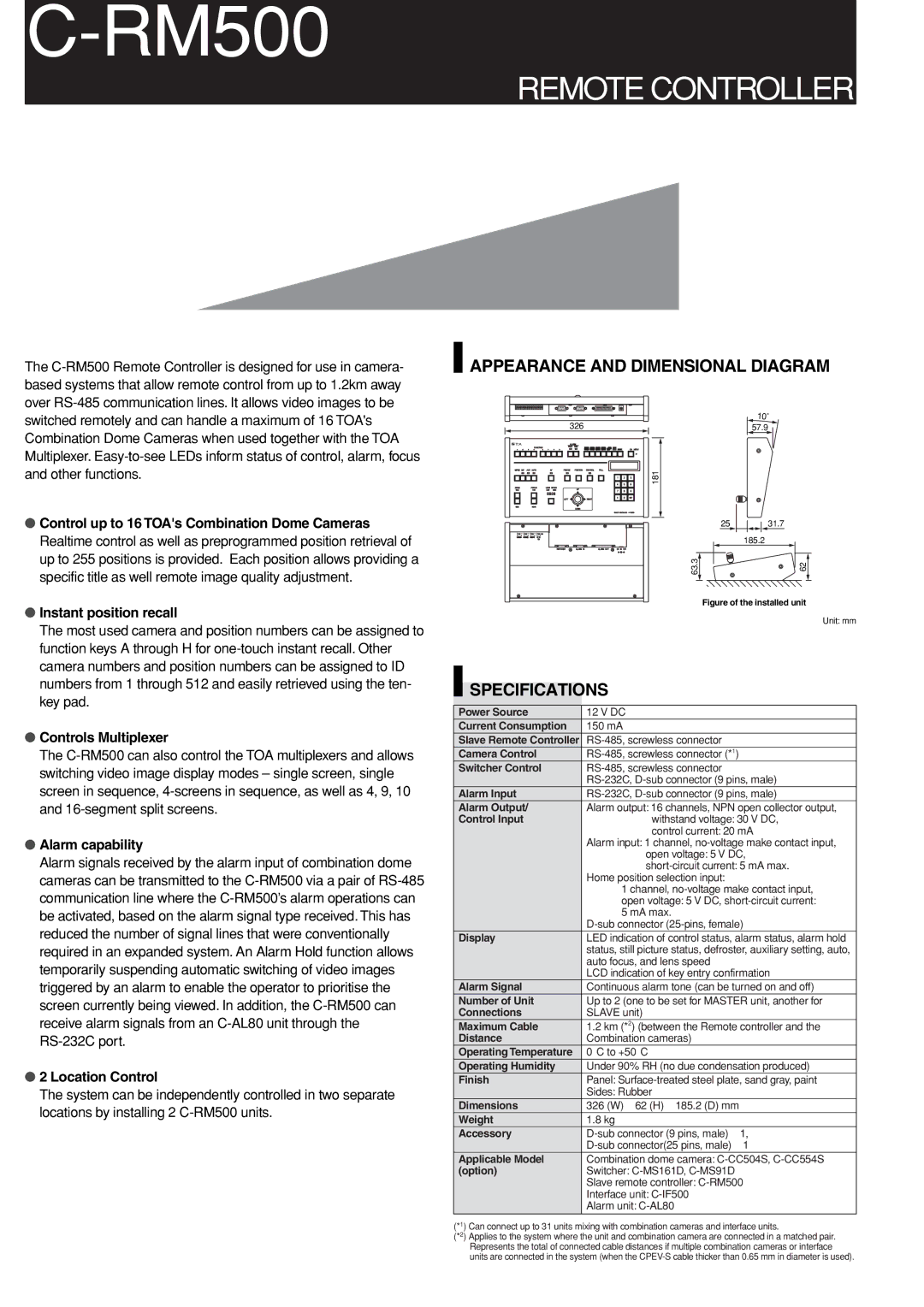
 APPEARANCE AND DIMENSIONAL DIAGRAM
Combination Dome Cameras when used together with the TOA Multiplexer.
● Control up to 16 TOA's Combination Dome Cameras |
Realtime control as well as preprogrammed position retrieval of |
up to 255 positions is provided. Each position allows providing a |
specific title as well remote image quality adjustment. |
326
181
63.3
57.9
2531.7
185.2
62
● Instant position recall |
The most used camera and position numbers can be assigned to |
function keys A through H for |
camera numbers and position numbers can be assigned to ID |
numbers from 1 through 512 and easily retrieved using the ten- |
key pad. |
● Controls Multiplexer |
The |
switching video image display modes – single screen, single |
screen in sequence, |
and |
● Alarm capability |
Alarm signals received by the alarm input of combination dome |
cameras can be transmitted to the |
communication line where the |
be activated, based on the alarm signal type received. This has |
reduced the number of signal lines that were conventionally |
required in an expanded system. An Alarm Hold function allows |
temporarily suspending automatic switching of video images |
triggered by an alarm to enable the operator to prioritise the |
screen currently being viewed. In addition, the |
receive alarm signals from an |
● 2 Location Control |
The system can be independently controlled in two separate |
locations by installing 2 |
|
|
|
| Figure of the installed unit |
|
|
|
| |
|
|
|
| Unit: mm |
|
|
|
|
|
|
|
|
|
|
| SPECIFICATIONS | |||
|
|
|
|
|
Power Source | 12 V DC | |||
Current Consumption | 150 mA | |||
Slave Remote Controller | ||||
Camera Control | ||||
Switcher Control | ||||
|
|
| ||
Alarm Input | ||||
Alarm Output/ | Alarm output: 16 channels, NPN open collector output, | |||
Control Input |
| withstand voltage: 30 V DC, | ||
|
|
|
| control current: 20 mA |
|
|
| Alarm input: 1 channel, | |
|
|
|
| open voltage: 5 V DC, |
|
|
|
| |
|
|
| Home position selection input: | |
|
|
| 1 channel, | |
|
|
| open voltage: 5 V DC, | |
|
|
| 5 mA max. | |
|
|
| ||
Display | LED indication of control status, alarm status, alarm hold | |||
|
|
| status, still picture status, defroster, auxiliary setting, auto, | |
|
|
| auto focus, and lens speed | |
|
|
| LCD indication of key entry confirmation | |
Alarm Signal | Continuous alarm tone (can be turned on and off) | |||
Number of Unit | Up to 2 (one to be set for MASTER unit, another for | |||
Connections | SLAVE unit) | |||
Maximum Cable | 1.2 km (*2) (between the Remote controller and the | |||
Distance | Combination cameras) | |||
Operating Temperature | 0°C to +50°C | |||
Operating Humidity | Under 90% RH (no due condensation produced) | |||
Finish | Panel: | |||
|
|
| Sides: Rubber | |
Dimensions | 326 (W) ⋅ 62 (H) ⋅ 185.2 (D) mm | |||
Weight | 1.8 kg | |||
Accessory | ||||
|
|
| ||
Applicable Model | Combination dome camera: | |||
(option) | Switcher: | |||
|
|
| Slave remote controller: | |
|
|
| Interface unit: | |
|
|
| Alarm unit: | |
(*1) Can connect up to 31 units mixing with combination cameras and interface units.
(*2) Applies to the system where the unit and combination camera are connected in a matched pair. Represents the total of connected cable distances if multiple combination cameras or interface units are connected in the system (when the
