|
|
|
INTERFACE UNIT |
| ALARM UNIT |
A useful option for configuring camera systems, the
The
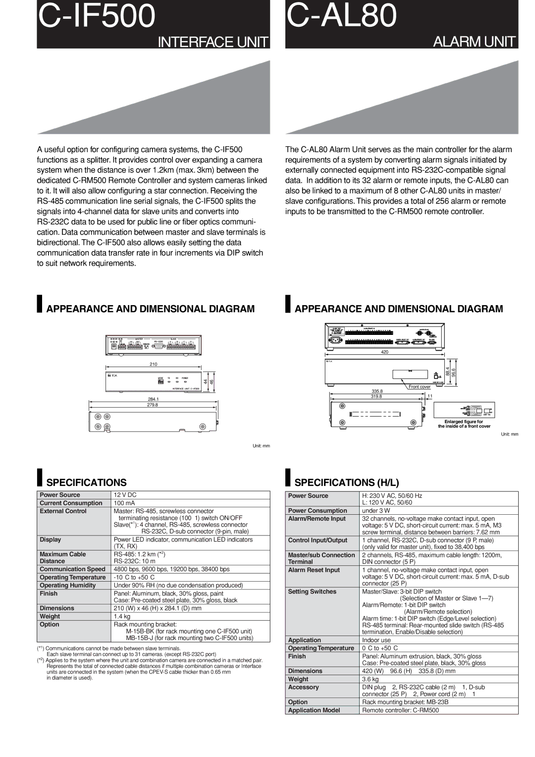
APPEARANCE AND DIMENSIONAL DIAGRAM |
| APPEARANCE AND DIMENSIONAL DIAGRAM | |||||||||||||||||||||||||||
|
|
|
|
|
|
|
|
|
|
|
|
|
|
|
|
|
|
|
|
|
|
|
|
|
|
|
|
|
|
|
|
|
|
|
|
|
|
|
|
|
|
|
|
|
|
|
|
|
|
|
|
|
|
|
|
|
|
|
|
|
|
|
|
|
|
|
|
|
|
|
|
|
|
|
|
|
|
|
|
|
|
|
|
|
|
|
|
|
|
|
|
|
|
|
|
|
|
|
|
|
|
|
|
|
|
|
|
|
|
|
|
|
|
|
|
|
|
|
|
|
|
|
|
|
|
|
|
|
|
|
|
|
|
|
|
|
|
|
|
|
|
|
|
|
|
|
|
|
|
|
|
|
|
|
|
|
|
|
|
|
|
|
|
|
|
|
|
|
|
|
|
|
|
|
|
|
|
|
|
|
|
|
|
|
|
|
|
|
|
|
|
|
|
|
|
|
|
|
|
|
|
|
|
|
|
|
|
|
|
|
|
|
|
|
|
|
|
|
|
|
|
|
|
|
|
|
|
|
|
|
|
|
|
|
|
|
|
|
|
210
|
|
|
|
|
|
|
|
|
|
|
|
|
| 44 |
| 46 |
| ||
|
|
|
|
|
| ||||
|
|
|
|
|
|
|
|
|
|
|
|
|
|
|
|
|
|
|
|
|
|
|
|
|
|
|
|
|
|
284.1
279.8
Unit: mm
420
88.4 | 96.6 |
Front cover
335.8
319.811
Enlarged figure for the inside of a front cover
Unit: mm
 SPECIFICATIONS
Power Source | 12 V DC |
Current Consumption | 100 mA |
External Control | Master: |
| terminating resistance (100 Ω) switch ON/OFF |
| Slave(*1): 4 channel, |
| |
Display | Power LED indicator, communication LED indicators |
| (TX, RX) |
Maximum Cable | |
Distance | |
Communication Speed | 4800 bps, 9600 bps, 19200 bps, 38400 bps |
Operating Temperature | |
Operating Humidity | Under 90% RH (no due condensation produced) |
Finish | Panel: Aluminum, black, 30% gloss, paint |
| Case: |
Dimensions | 210 (W) x 46 (H) x 284.1 (D) mm |
Weight | 1.4 kg |
Option | Rack mounting bracket: |
| |
|
|
(*1) Communications cannot be made between slave terminals.
Each slave terminal can connect up to 31 cameras. (except
(*2) Applies to the system where the unit and combination camera are connected in a matched pair. Represents the total of connected cable distances if multiple combination cameras or Interface units are connected in the system (when the
in diameter is used).
 SPECIFICATIONS (H/L)
Power Source | H: 230 V AC, 50/60 Hz |
| L: 120 V AC, 50/60 |
Power Consumption | under 3 W |
Alarm/Remote Input | 32 channels, |
| voltage: 5 V DC, |
| screw terminal, distance between barriers: 7.62 mm |
Control Input/Output | 1 channel, |
| (only valid for master unit), fixed to 38,400 bps |
Master/sub Connection | 2 channels, |
Terminal | DIN connector (5 P) |
Alarm Reset Input | 1 channel, |
| voltage: 5 V DC, |
| connector (25 P) |
Setting Switches | Master/Slave: |
| (Selection of Master or Slave |
| Alarm/Remote: |
| (Alarm/Remote selection) |
| Alarm time: |
| |
| termination, Enable/Disable selection) |
Application | Indoor use |
Operating Temperature | 0°C to +50°C |
Finish | Panel: Aluminum extrusion, black, 30% gloss |
| Case: |
Dimensions | 420 (W) ⋅ 96.6 (H) ⋅ 335.8 (D) mm |
Weight | 3.6 kg |
Accessory | DIN plug ⋅ 2, |
| connector (25 P) ⋅ 2, Power cord (2 m) ⋅ 1 |
Option | Rack mounting bracket: |
Application Model | Remote controller: |