6. OPERATION
Step 1. Turn on the power of both the
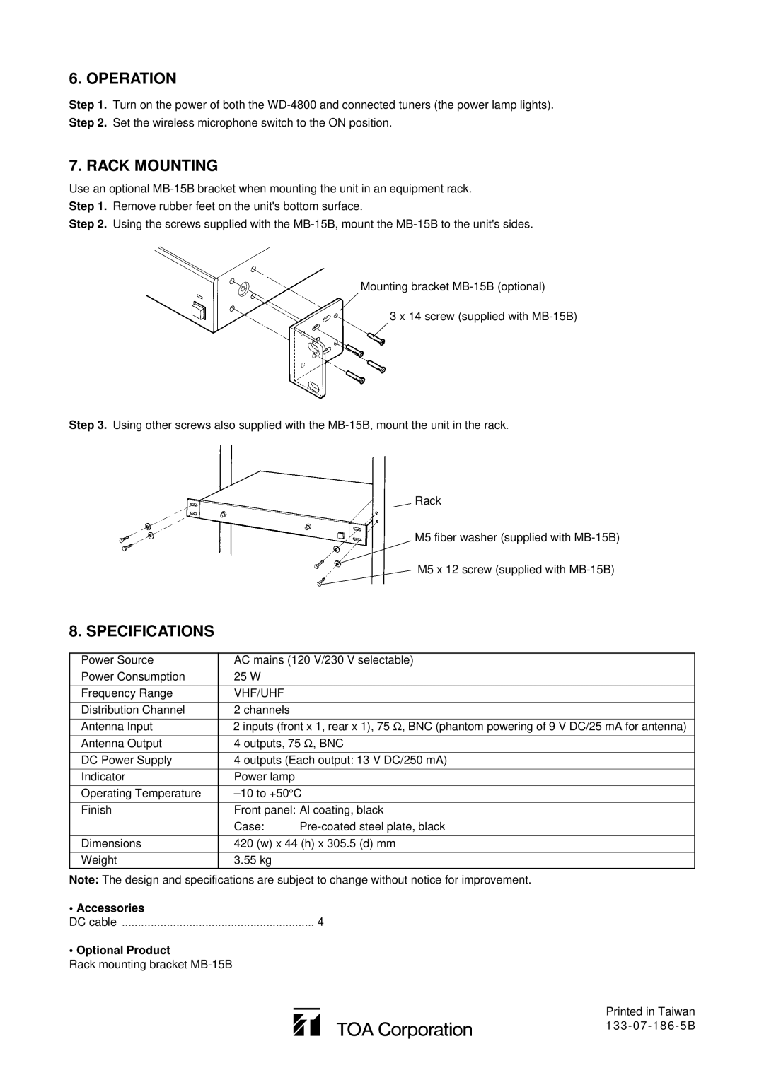
7. RACK MOUNTING
Use an optional
Step 1. Remove rubber feet on the unit's bottom surface.
Step 2. Using the screws supplied with the
Mounting bracket
3 x 14 screw (supplied with
Step 3. Using other screws also supplied with the
Rack
M5 fiber washer (supplied with
M5 x 12 screw (supplied with
8. SPECIFICATIONS
Power Source | AC mains (120 V/230 V selectable) | |
|
|
|
Power Consumption | 25 W |
|
|
|
|
Frequency Range | VHF/UHF |
|
|
|
|
Distribution Channel | 2 channels |
|
|
| |
Antenna Input | 2 inputs (front x 1, rear x 1), 75 Ω , BNC (phantom powering of 9 V DC/25 mA for antenna) | |
Antenna Output | 4 outputs, 75 Ω , BNC | |
DC Power Supply | 4 outputs (Each output: 13 V DC/250 mA) | |
|
|
|
Indicator | Power lamp |
|
|
| |
Operating Temperature | ||
|
| |
Finish | Front panel: Al coating, black | |
| Case: | |
|
| |
Dimensions | 420 (w) x 44 (h) x 305.5 (d) mm | |
|
|
|
Weight | 3.55 kg |
|
|
|
|
Note: The design and specifications are subject to change without notice for improvement.
• Accessories |
|
DC cable | 4 |
• Optional Product |
|
Rack mounting bracket |
|
Printed in Taiwan