II. INSTALLATION
IMPORTANT
IT IS THE CUSTOMER’S RESPONSIBILITY TO REPORT ANY CONCEALED OR
A.Installation Options and Kit Availability
The installation instructions in this Manual are for a single toaster oven using the supplied legs. A stacking kit (P/N T2114STACK) is available from Toastmaster for 2- and
CAUTION
STACKING MORE THAN THREE OVENS IS NOT PERMITTED.
B.Assembly
If you are installing the oven as part of a stacked installation, REFER TO THE STACKING KIT INSTRUCTIONS or contact Toastmaster for assistance.
1.Installing the Legs
a.Carefully tilt the oven onto its rear side so that the front (control) side faces directly upwards. See Figure 2.
b.Thread the four legs into the four holes provided on the bottom of the oven. Tighten them until they are secure. See Figure 2.
CAUTION
THE SUPPLIED LEGS MUST BE FASTENED IN PLACE PRIOR TO OPERATING THE OVEN.
Figure 2
2.Installing the Conveyor End Trays
a.Press one of the conveyor end trays down over the end plate of the conveyor frame. See Figure 3. The end tray should extend outward from the end of the conveyor, and its sides should be flush with the sides of the conveyor frame.
b.Fasten the end tray in place with one of the supplied
c.Repeat these steps to install the second end tray at the opposite end of the conveyor frame.
CAUTION
THE CONVEYOR END TRAYS MUST BE FASTENED IN PLACE PRIOR TO OPERATING THE OVEN.
| Figure 3 |
1. Position tray | 2. Fasten in place |
| with screw |
C.Electrical Utility Connection
IMPORTANT
THE ELECTRICAL CONNECTION TO THE OVEN REQUIRES A CIRCUIT BREAKER/FUSED DISCONNECT. ELECTRICAL SPECIFICATIONS ARE LISTED ON THE SERIAL PLATE (SHOWN IN FIGURE 4), AND ON THE WIRING DIAGRAMS AT THE BACK OF THIS MANUAL.
CONSULT ALL APPLICABLE NATIONAL AND LOCAL CODES FOR FURTHER ELECTRICAL CONNECTION REQUIREMENTS.
1.Before proceeding with the electrical connection, check the following:
a.Check that the electrical supply matches the oven’s require- ments. Refer to the serial plate (Figure 4) and to the electrical specifications on the wiring diagrams at the back of this Manual.
b.Check that the appropriate receptacle is available for the power cord plug.
WARNING
ENSURE THAT BOTH THE CIRCUIT BREAKER/FUSED DIS- CONNECT AND THE POWER ON/OFF (“I/O”) SWITCH ARE IN THE OFF (“O”) POSITION BEFORE PROCEEDING.
WARNING
ENSURE THAT ANY PACKING MATERIAL RESIDUE HAS BEEN REMOVED FROM INSIDE THE COOKING CHAMBER.
3.Insert the power cord plug into its receptacle.
Figure 4
Serial plate
III. OPERATION
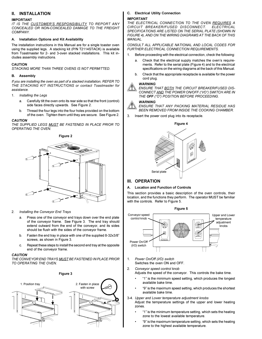
A.Location and Function of Controls
This section provides a basic description of the oven controls, their location, and the functions they perform. The operator MUST be familiar with the controls. Refer to Figure 5.
| Figure 5 |
Conveyor speed | Upper and Lower |
control knob | temperature |
| adjustment |
| knobs |
Power On/Off |
|
(I/O) switch |
|
1.Power On/Off (I/O) switch Switches the oven ON and OFF.
2.Conveyor speed control knob
Adjusts the speed of the conveyor. This controls the bake time.
•“1” is the minimum speed setting, which produces the longest available bake time.
•“9” is the maximum speed setting, which produces the shortest available bake time.
3-4. Upper and Lower temperature adjustment knobs
Adjust the temperature settings of the upper and lower heating zones.
•“1” is the minimum temperature setting, which sets the heating zone to the lowest available temperature.
•“9” is the maximum temperature setting, which sets the heating zone to the highest available temperature.