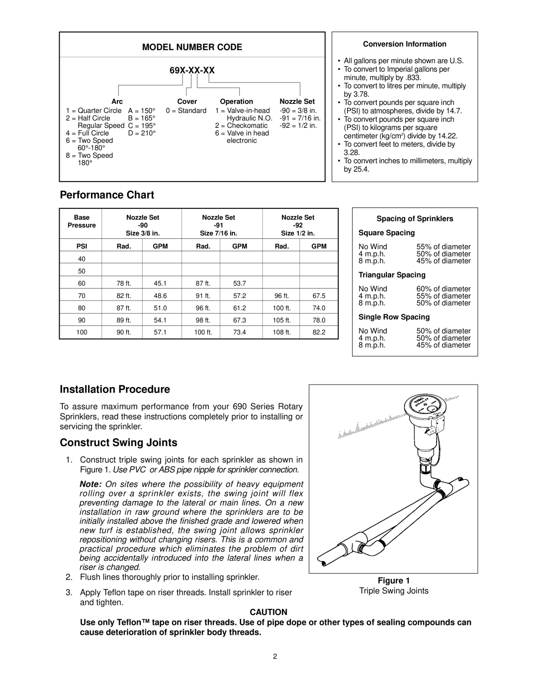
69X-01-XX, 69X-02-XX, 69X-06-XX specifications
The Toro 69X series, comprising models 69X-01-XX, 69X-02-XX, and 69X-06-XX, represents the pinnacle of modern landscaping technology. These innovative machines are designed to enhance efficiency and performance in various landscaping tasks while prioritizing user comfort and environmental sustainability.One of the main features of the Toro 69X series is its robust engine performance. Equipped with a high-efficiency powertrain, these models ensure optimal torque and power delivery, enabling users to tackle challenging terrain and heavy workloads with ease. The engine's design minimizes fuel consumption, which not only reduces operating costs but also contributes to a lower carbon footprint, aligning with contemporary environmental standards.
In addition to powerful engines, the Toro 69X series boasts an advanced cutting system that enhances precision and consistency in lawn maintenance. The cutting decks are engineered for versatility, allowing for a wide range of adjustments to accommodate different grass types and conditions. This adaptability ensures that users achieve the highest quality cuts while minimizing clippings left behind.
Another significant characteristic of the Toro 69X series is its user-friendly design. Incorporating ergonomic features, such as comfortable seating and intuitive controls, the series prioritizes the operator's experience. The controls are strategically placed for easy access, reducing strain during long hours of operation. Furthermore, the models are equipped with advanced display systems, providing real-time data on machine performance and maintenance requirements, ensuring optimal operational efficiency.
The Toro 69X-02-XX, in particular, features all-wheel drive technology, providing exceptional traction and stability on uneven surfaces. This feature is ideal for residential properties with inclines or commercial landscaping projects that demand a reliable and agile machine. The all-wheel drive system allows for seamless transitions from flat to sloped areas, enhancing the overall performance and safety of the operation.
Safety is another critical aspect of the Toro 69X series design. Integrated safety features, such as roll-over protection systems and automatic shut-off mechanisms, ensure that both the operator and the machine are safeguarded during operation. This focus on safety aligns with Toro's commitment to delivering high-quality equipment that meets rigorous industry standards.
In summary, the Toro 69X series, with its distinctive models 69X-01-XX, 69X-02-XX, and 69X-06-XX, stands out for its powerful performance, innovative cutting technology, user-centric design, and safety features. These advanced landscaping solutions not only enhance productivity but also ensure an enjoyable and safe user experience, making them a reliable choice for professionals and landscaping enthusiasts alike.

