Getting Started
Getting started
Exploring your new TV (continued)
TV back
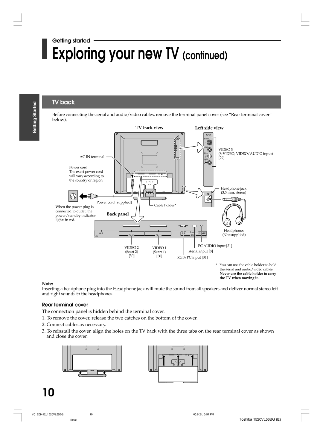
Before connecting the aerial and audio/video cables, remove the terminal panel cover (see “Rear terminal cover” below).
TV back view | Left side view |
| VIDEO 3 |
AC IN terminal | |
[29] |
Power cord
The exact power cord will vary according to the country or region.
Headphone jack (3.5 mm, stereo)
| Power cord (supplied) |
When the power plug is | Cable holder* |
|
connected to outlet, the | Back panel |
|
|
power/standby indicator |
|
| |
lights in red. |
|
|
|
|
|
| Headphones |
|
|
| (Not supplied) |
| VIDEO 2 | VIDEO 1 | PC AUDIO input [31] |
| Aerial input [8] | ||
| (Scart 2) | (Scart 1) | |
| [30] | [30] | RGB/PC input [31] |
|
|
| |
|
|
| * You can use the cable holder to hold |
|
|
| the aerial and audio/video cables. |
|
|
| Never use the cable holder to carry |
|
|
| the TV when moving it. |
Note:
Inserting a headphone plug into the Headphone jack will mute the sound from all speakers and deliver normal stereo left and right sounds to the headphones.
Rear terminal cover
The connection panel is hidden behind the terminal cover.
1.To remove the cover, release the two catches on the bottom of the cover.
2.Connect cables as necessary.
3.To reinstall the cover, align the holes on the TV back with the three tabs on the rear terminal cover as shown and close the cover.
10
10 | 05.6.24, 0:51 PM |
Black
Toshiba 1520VL56BG (E)