TOSHIBA G3 APPLICATION GUIDELINE 21.5
Direction Change with RX Input (page 1 of 2)
Introduction
Like all speed references on the G3, the RX input has an adjustable bias and gain. The RX is unique, however, in that its inputs can be positive or negative and the corresponding speeds can be positive or negative. The first example shown below will allow a motor direction change based on a
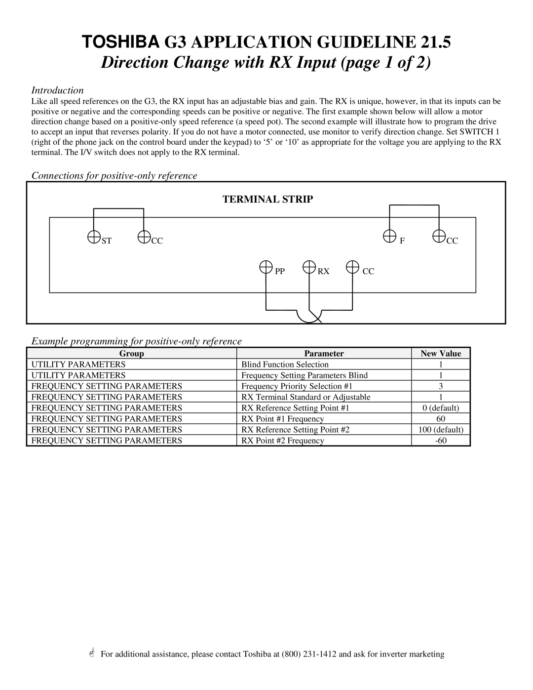
Connections for positive-only reference
| TERMINAL STRIP |
|
|
|
ST | CC |
| F | CC |
| PP | RX | CC |
|
Example programming for positive-only reference
Group | Parameter | New Value |
UTILITY PARAMETERS | Blind Function Selection | 1 |
UTILITY PARAMETERS | Frequency Setting Parameters Blind | 1 |
FREQUENCY SETTING PARAMETERS | Frequency Priority Selection #1 | 3 |
FREQUENCY SETTING PARAMETERS | RX Terminal Standard or Adjustable | 1 |
FREQUENCY SETTING PARAMETERS | RX Reference Setting Point #1 | 0 (default) |
FREQUENCY SETTING PARAMETERS | RX Point #1 Frequency | 60 |
FREQUENCY SETTING PARAMETERS | RX Reference Setting Point #2 | 100 (default) |
FREQUENCY SETTING PARAMETERS | RX Point #2 Frequency |
*For additional assistance, please contact Toshiba at (800)