Tecra 750 Series Disassembly Overview, (cont.)
î
To install the middle frame, follow the steps below.
1.Reroute the cables and replace the probe pin harness.
2.Secure the probe pin harness to the middle frame with two M2x5 screws.
3.Secure the bracket over the probe pin harness with one M2x3 screw.
4.Make sure the Selectable Bay release lever is extended and the Selectable Bay lock is in the lock position.
5.Seat the middle frame and make sure a small tongue on the middle frame’s Selectable Bay locking mechanism fits into a corresponding notch on the external Selectable Bay lock.
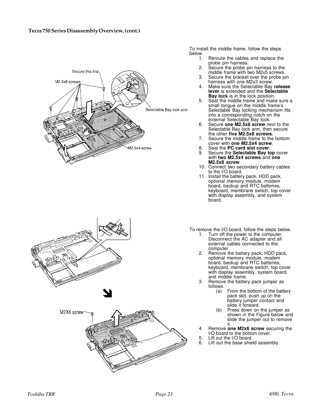
6.Secure one M2.5x8 screw next to the Selectable Bay lock arm, then secure the other five M2.5x8 screws.
7.Secure the middle frame to the bottom cover with one M2.5x4 screw.
8.Seat the PC card slot cover.
9.Secure the Selectable Bay top cover with two M2.5x4 screws and one M2.5x8 screw.
10.Connect two secondary battery cables to the I/O board.
11.Install the battery pack, HDD pack, optional memory module, modem board, backup and RTC batteries, keyboard, membrane switch, top cover with display assembly, and system board.
To remove the I/O board, follow the steps below.
1.Turn off the power to the computer. Disconnect the AC adapter and all external cables connected to the computer.
2.Remove the battery pack, HDD pack, optional memory module, modem board, backup and RTC batteries, keyboard, membrane switch, top cover with display assembly, system board, and middle frame.
3.Remove the battery pack jumper as follows:
(a)From the bottom of the battery pack slot, push up on the battery jumper contact and slide it forward.
(b)Press down on the jumper as shown in the Figure below and slide the jumper out to remove it.
4.Remove one M2x6 screw securing the I/O board to the bottom cover.
5.Lift out the I/O board.
6.Lift out the base shield assembly.
Toshiba TRR | Page 23 | 4/00, Tecra |