Tecra 750 Series Disassembly Overview, (cont.)
ê
NOTE: Be careful not to apply pressure to the ICs along the edge of the LCD module.
The ICs are easily damaged.
To remove the LCD module, follow the steps below.
1.Turn off the power to the computer. Disconnect the AC adapter and all external cables connected to the computer.
2.Remove the battery pack, display mask, and FL inverter board.
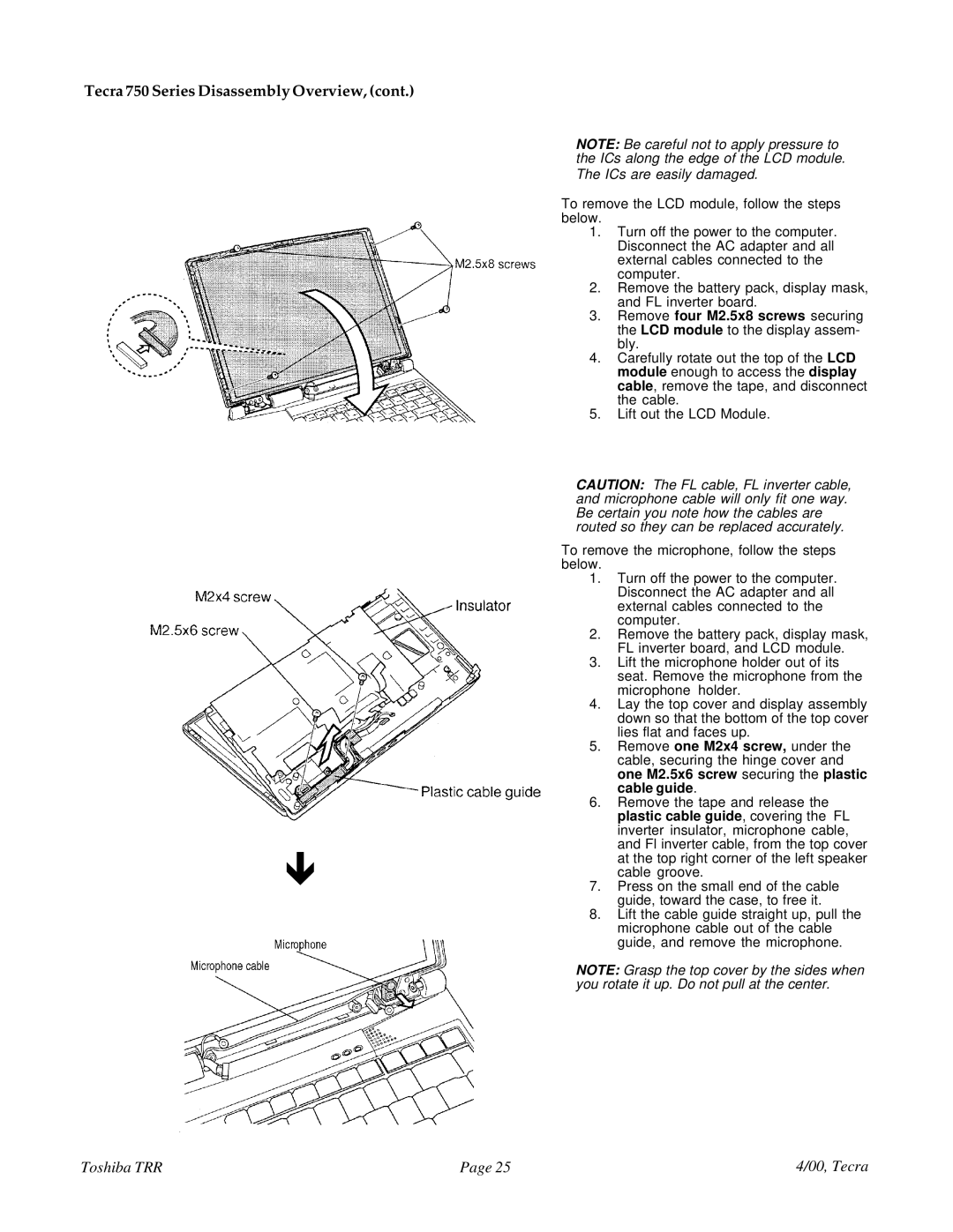
3.Remove four M2.5x8 screws securing the LCD module to the display assem- bly.
4.Carefully rotate out the top of the LCD module enough to access the display cable, remove the tape, and disconnect the cable.
5.Lift out the LCD Module.
CAUTION: The FL cable, FL inverter cable, and microphone cable will only fit one way. Be certain you note how the cables are routed so they can be replaced accurately.
To remove the microphone, follow the steps below.
1.Turn off the power to the computer. Disconnect the AC adapter and all external cables connected to the computer.
2.Remove the battery pack, display mask, FL inverter board, and LCD module.
3.Lift the microphone holder out of its seat. Remove the microphone from the microphone holder.
4.Lay the top cover and display assembly down so that the bottom of the top cover lies flat and faces up.
5.Remove one M2x4 screw, under the cable, securing the hinge cover and one M2.5x6 screw securing the plastic cable guide.
6.Remove the tape and release the plastic cable guide, covering the FL inverter insulator, microphone cable, and Fl inverter cable, from the top cover at the top right corner of the left speaker cable groove.
7.Press on the small end of the cable guide, toward the case, to free it.
8.Lift the cable guide straight up, pull the microphone cable out of the cable guide, and remove the microphone.
NOTE: Grasp the top cover by the sides when you rotate it up. Do not pull at the center.
Toshiba TRR | Page 25 | 4/00, Tecra |