2. MAJOUR UNIT REPLACEMENT
2.5. REPLACING THE MEDIA SENSOR
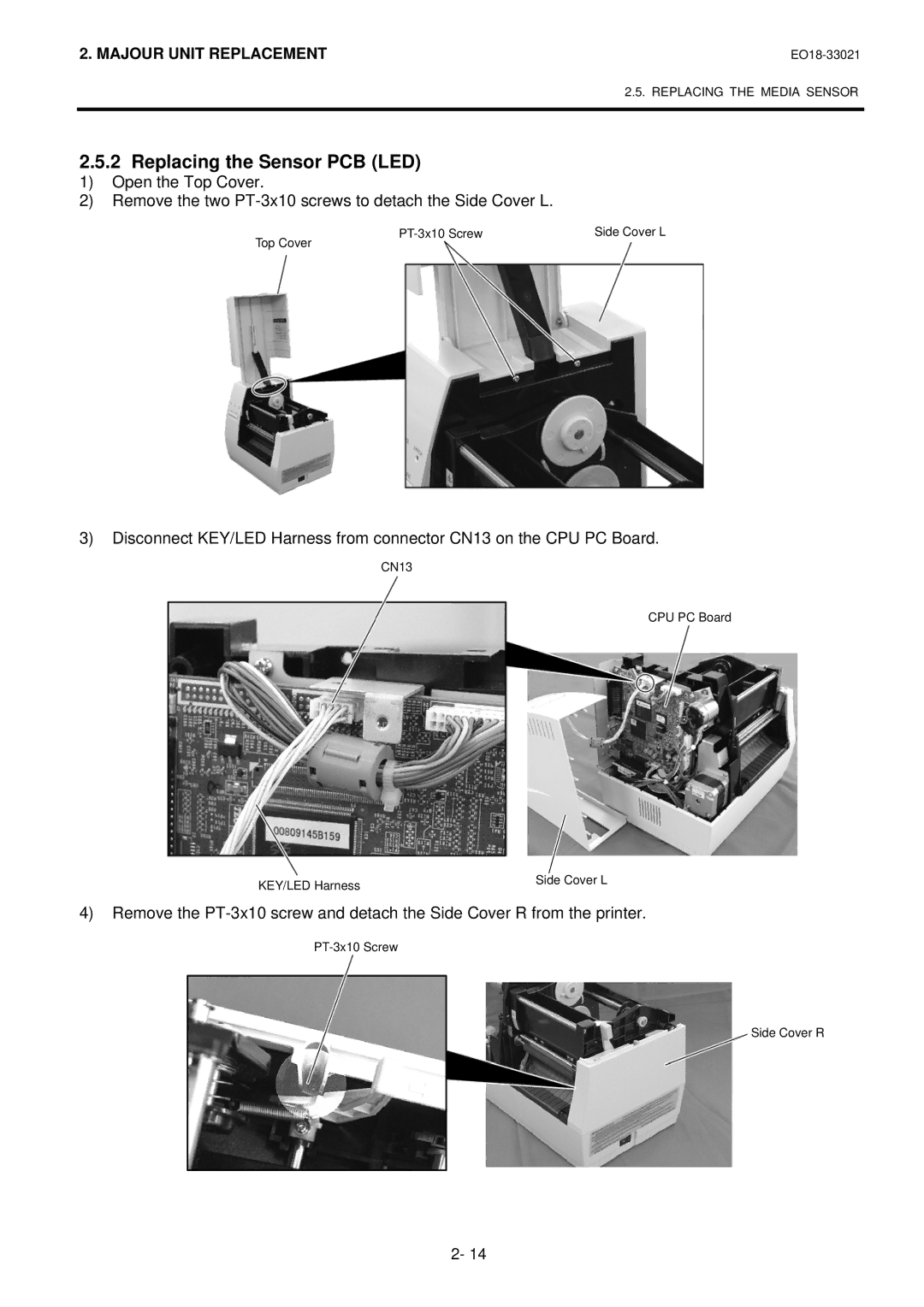
2.5.2 Replacing the Sensor PCB (LED)
1)Open the Top Cover.
2)Remove the two
Top Cover | Side Cover L | |
|
|
3)Disconnect KEY/LED Harness from connector CN13 on the CPU PC Board.
CN13
CPU PC Board
KEY/LED Harness | Side Cover L |
|
4)Remove the
Side Cover R
2- 14