SV4D-GS/GC10-QM
Table of Contents
Receive Buffer Free Space Status Request Command
Commands for System Administrator
Errors in Writable Character and PC Command Save Modes
183
11.1
11.2
190
Flash ROM Memory
SV4D
Dram
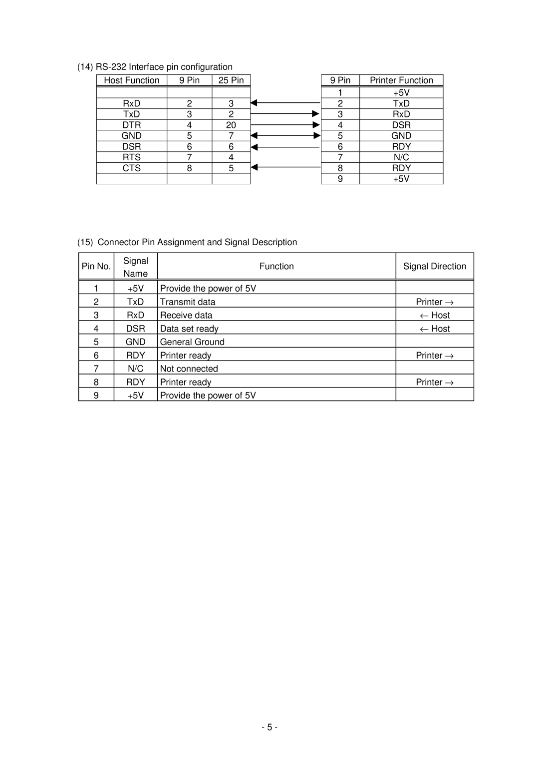
Standard RS-232C Interface Centronics
Interface
Page
Page
DSR GND RDY
DTR GND DSR RTS CTS
57RE-40360-73B or equivalent
DDK
Cable Amp. Japan Or equivalent
57E-30360 or equivalent
Chassis GND
Fault
\COPY XXXXXX.NEW /B LPT1
KEY Operation Functions
Transmission control Forward feed wait Control code
None
Auto
Feed key function
Transmission Sequence
Page
Label Issue Operation
Page
Command & Data
Format of Interface command
ESC
NUL
Page
Print Density Fine Adjust Command
Commands related to setting Label Size Set Command
Commands related to clear Image Buffer Clear Command
Clear Area Command
Label Size SET Command ESC D
Commands for Creating Application
Labels Tags
Tags
SV4D
Page
Examples Labels Tags
Position Fine Adjust Command ESC AX
+3.0 mm
First print position home position after back feed
Cut position or strip position fine adjustment ±35.0 mm
±50.0 mm
±9.9 mm
Examples Cut issue
ESC AX +010, +020, +00 LF NUL
ESC T20D30 LF NUL
Print Density Fine Adjust Command ESC AY
Image Buffer Clear Command ESC C
Clear Area Command ESC XR
Effective print area
Line Format Command ESC LC
Line Horizontal line In the case of Y2 Y1 =
Vertical line In the case of X2 X1 =
Slant line a X 2 X 1 ≤ Y 2 Y Slant line B X 2 X 1 Y 2 Y
Radius of rounded corners ≠
Origin 0 28.0 mm 20.0 mm 30.5 mm
BIT MAP Font Format Command ESC PC
Page
Page
Sample
Horizontal magnification and vertical magnification
Relationship between drawing coordinates and magnification
180 270 Selection of character attribution
Rotational angles of a character and character string
Black characters Reverse characters
Boxed characters Stroked out characters
INC/DEC
A2A0A INC/DEC
A0A0A
A2A0A
A0A1A
Abcd
Page
Page
C D
Origin 0
Outline Font Format Command ESC PV
Page
Page
Page
180 270
Sample
Character width and character height
180 270 Selection of character attribution
INC/DEC
ABC
Page
Page
Origin 0 12.5 30.0
Origin 0
KIX Code
BAR Code Format Command ESC XB
CODE93
UPC-A
CODE128 Pseudo
WPC
CODE128 Pseudo UCC/EAN128
Postnet
Page
CODE39
MSI
ITF
Page
Rectangular code
Page
Page
Page
Parameter No. of columns No. of rows
Oo20
Page
Origin Coordinates Effective Backing paper
UPC-A + 2 digits
KIX code MaxiCode
Postnet RM4SCC
JAN, EAN, UPC CODE93
Type of bar code Narrow Wide Character-to-character
MSI ITF CODE39 NW7
Case of QR code
Postal code
Bar code height
CIn the case of JAN and EAN Example EAN13 + 2 digits
INC/DEC
No. of zeros to be suppressed
Abcd
Page
Cell size and the effective data capacity
Explanation for QR code cError correction level
For MaxiCode, data can be divided into a max. of 8 codes
D1-cell width
Page
Page
Origin 0 12.5
Origin 0
Origin 0 12.5 mm 55.5 mm 20.0 mm 83.0 mm
@ Link Field Data Command ESC RC ccc Ccc LF ddd Ddd LF
BIT MAP Font Data Command ESC RC
Function Provides data for the bit map font row Format Term
Bbb LF NUL
Sample
55.0 20.0 mm 65.0 mm Effective print area
Function Provides data for the outline font row Format
Outline Font Data Command ESC RV
Sample
20.0 mm Effective print area 65.0 mm
Function Provides data for the bar code Format
BAR Code Data Command ESC RB
11 digits
Royal Mail 4 State Customer Code 12 digits
Page
102
Cell Size and Effective Data Capacity
Sets the security level automatically
Parameter No. of columns No. of rows
Page
Conditions causing an error cNo start code is designated
Page
Transfer code for QR code
Class of service Fixed as 3 digits Numerics
Country code Fixed as 3 digits Numerics
109
12.5 mm 15.0 mm 55.0 mm 20.0 mm 63.0 mm Effective print area
30.0
Origin 0 12.5 mm 55.5 mm 20.0 mm 83.0 mm
Issue Command ESC XS
Page
Issue mode Batch mode cut interval
Cut position Head position
Strip mode Issue count
Sec 118
Labels Tags 119
Labels Tags Printing top first
Labels Mirror printing top first
Sensor used
Issue count Pieces Cut interval Paper Tag paper Reflective
Stop position after feeding one label
Paper is moved in the above state
Feed Command ESC T
Head position
Strip position Head position
SV4D
M p l e
ESC IB LF NUL
Eject Command ESC IB
ESC U1, ESC U2
FORWARD/REVERSE Feed Command
AA a AAA
Storage Area Allocate Command ESC XF
Page
ESC J1
Memory Board Format Command
19 2-BYTE Writable Character Code Range Command ESC XE
BIT MAP Writable Character Command ESC XD
Page
= Writable character
Nibble mode
Hex. mode
Writable character set 01 to 40, 51 to
Page
Writable character set 41 16×16 dots
Writable character set 42 24×24 dots
Writable character set 43 32×32 dots
Writable character set 44 48×48 dots
Page
Examples Writable character set Writable character code 70H
Graphic Command ESC SG
Backing paper Origin Label
66 00H
Not present Present
When Topix compression mode is selected
Data after being compressed Line No Graphic data
151
37H = 3FH = ? 152
Topix compression mode
Save Start Command ESC XO
ESC XP LF NUL
Save Terminate Command ESC XP
Saved Data Call Command ESC XQ
ESC WR LF NUL
Reset Command ESC WR
ESC WS LF NUL
Status Request Command ESC WS
ESC WB LF NUL
Receive Buffer Free Space Status Request Command ESC WB
3XH
3XH 0DH
161
ESC WV LF NUL
Version Information Acquire Command ESC WV
2DH
2EH
Memory Board Information Acquire Command ESC WI
Stored PC command save file name
Refer to Printer Information Request Command ESC IR 165
Printer Information Store Command ESC IG
SV4D-GS10-QM
Serial No 2303A000001
Refer to Printer Information Store Command ESC IG 166
Printer Information Request Command ESC IR
ESC IR LF NUL
Bytes
LATIN9
Parameter SET Command
None Even
ODD 167
Page
Page
Fine Adjustment Value SET Command
Sensor Transmissive
ESC Z0 zero
Batch Reset Command
Control Code Selection
Error Processing
Page
Errors in Writable Character and PC Command Save Modes
Status Format
Functions
SOH STX
ETX EOT
Printer Status
Detail Status
Printer Status Output Signal
Printer Status Output Signal
Parity error, overrun error
Online mode Yes Communicating Head was opened A pause state
Feed or an issue was
LED Indication
Feed
Character Code Table
Page
Page
Page
Page
Page
Page
Page
Page
Page
Page
Page
Page
Page
Page
Page
Page
Page
PC-850 201
TrueType Font
PC-852 PC-857 202
PC-851 PC-855 203
PC-1250 PC-1251 204
PC-1252 10 PC-1253 205
11 PC-1254 12 PC-1257 206
Arabic 207
LATIN9
WPC JAN, EAN, UPC
BAR Code Table
NW-7 CODE93 Transfer code Drawing code 209
CODE128 Transfer code
Start Code a Start Code B Start Code C
Drawing code Value Code Table 210
FNC4
102 FNC1 FNC1 FNC1
211
? How to send control code data
00H 3EH, 40H
01H 3EH, 41H
NUL
Details
215
Mode selection No. of data strings Data to be printed Digits
2 3 4 5 6, K Kanji data, B 0 0 1 0 a E o B C
? How to send control code data NUL 00H → @ 3EH, 40H
Postnet RM4SCC KIX Code
Postal code Customer bar code
BEL
218
SOH
CP code Transfer Code
Modulus 10 check
Auto affix of modulus
221
Auto affix of modulus 10 + price C/D 4 digits
Type of Bar Code JAN13, EAN13 No affix
Auto affix of modulus 10 + price C/D 5 digits
222
223
Type of Bar Code UPC-A No affix
224
Type of Bar Code UPC-E No affix
225
Type of Bar Code JAN8 +2 digits, EAN8 + 2 digits No affix
226
Type of Bar Code JAN8 +5 digits, EAN8 + 5 digits No affix
227
Type of Bar Code JAN13 +2 digits, EAN13 + 2 digits No affix
Type of Bar Code JAN13 +5 digits, EAN13 + 5 digits No affix
229
Type of Bar Code UPC-A + 2 digits No affix
230
Type of Bar Code UPC-A + 5 digits No affix
231
Type of Bar Code UPC-E + 2 digits No affix
232
Type of Bar Code UPC-E + 5 digits No affix
IBM modulus 10 check
Type of Bar Code MSI No affix
Auto affix of IBM modulus
IBM modulus 10 + Auto affix of IBM modulus
Type of Bar Code Interleaved 2 No affix
Auto affix of DBP modulus
234
Modulus check character check
Type of Bar Code Industrial 2 No affix
Auto affix of modulus check character
235
Type of Bar Code CODE39 Standard No affix
Modulus 43 check
236
Type of Bar Code NW7 No affix C/D check Auto affix
Type of Bar Code CODE39 Full Ascii No affix
238
239
Type of Bar Code CODE93 No affix C/D check Auto affix of C/D
Type of Bar Code RM4SCC Auto affix of dedicated C/D
Type of Bar Code Postnet Auto affix of dedicated C/D
Type of Bar Code KIX Code No affix
240
CC7
241
Automatic Adding of START/STOP Code
Input Data Drawing Data 12345ABC Standard Full Ascii