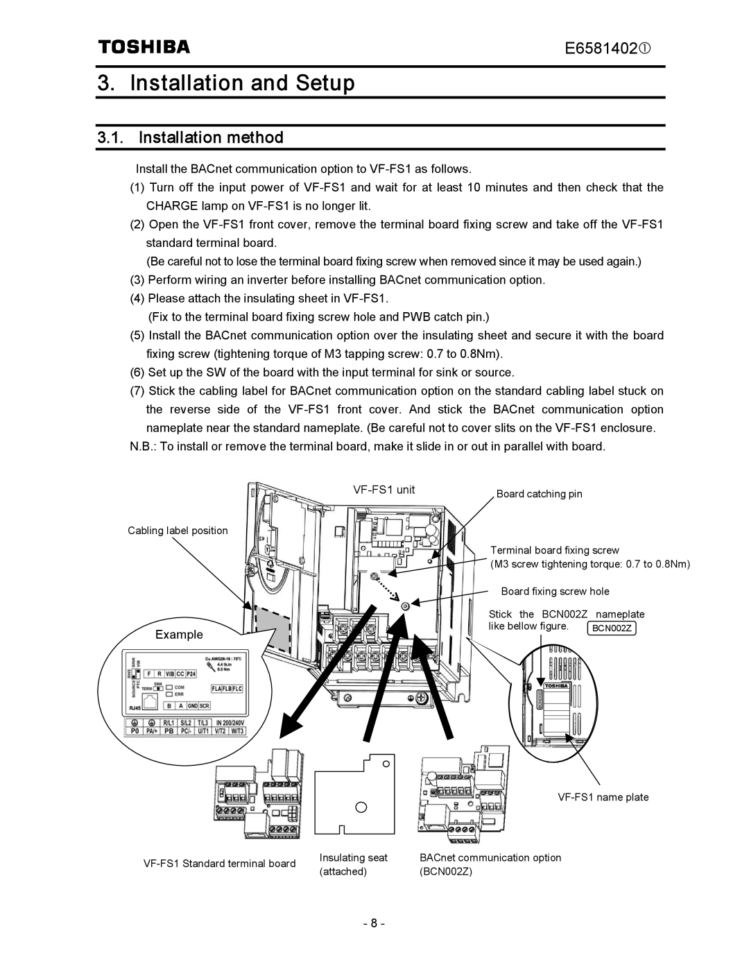
BCN002Z specifications
The Toshiba BCN002Z is a cutting-edge technology device designed to enhance user experience in various applications, particularly in the realm of entertainment and multimedia consumption. This compact yet powerful device is packed with a host of features aimed at delivering seamless performance and superior functionality.One of the standout characteristics of the BCN002Z is its sleek design, which not only makes it visually appealing but also ensures portability. Its lightweight form factor allows users to take it on the go, whether for business presentations, leisure activities, or multimedia streaming.
The device boasts advanced processing capabilities, thanks to its high-performance chipset. This ensures that users experience fast response times and smooth operation, even when handling multiple tasks simultaneously. The BCN002Z is designed to support high-definition content, making it suitable for video playback and gaming, allowing users to enjoy stunning visuals without any lag.
Connectivity is a major highlight of the Toshiba BCN002Z. It features multiple ports, including HDMI and USB, which enable users to connect various peripherals and external devices easily. This flexibility ensures that users can expand the functionality of their device, whether by connecting it to larger displays or external storage devices.
Additionally, the BCN002Z incorporates the latest wireless technologies, including Wi-Fi and Bluetooth, allowing users to connect to the internet and other devices effortlessly. This feature is particularly beneficial for streaming content from online platforms or transferring files between devices without the hassle of cables.
The Toshiba BCN002Z also emphasizes energy efficiency, making it an environmentally friendly choice. It is designed to consume less power without compromising performance, which helps in reducing energy costs for users.
In summary, the Toshiba BCN002Z is a versatile device that blends aesthetics and functionality. With its powerful processing capabilities, extensive connectivity options, and focus on energy efficiency, it caters to the needs of modern users looking for performance and convenience in a compact design. Whether for personal use or professional applications, the BCN002Z stands out as a reliable choice in the competitive tech landscape.

