Front Panel
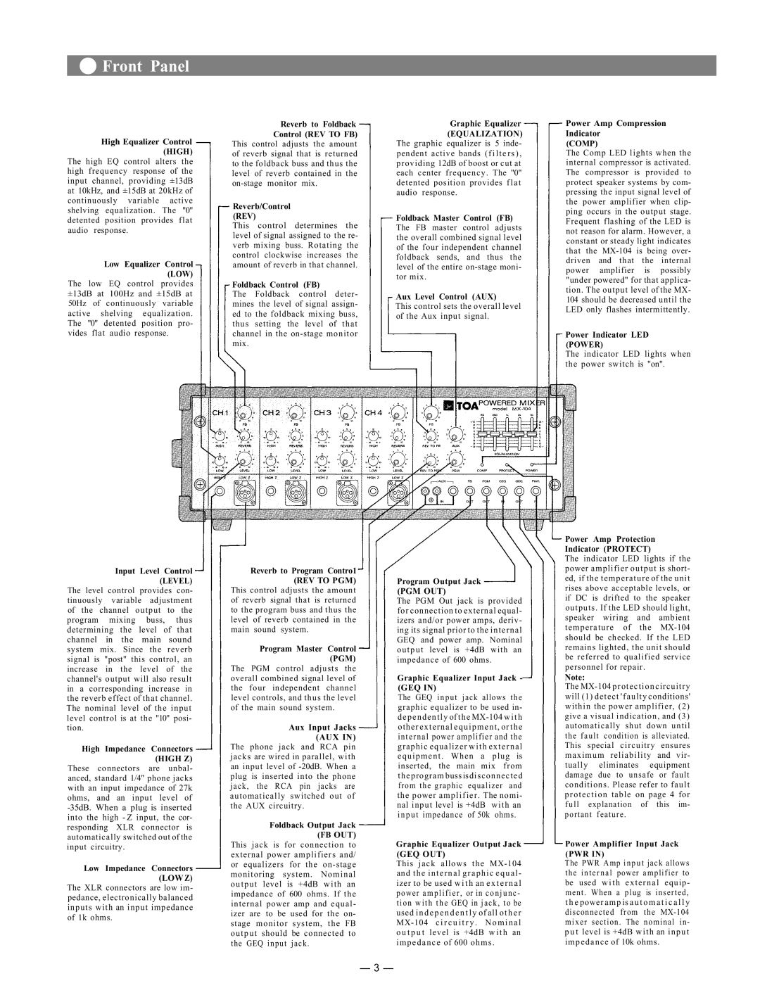
High Equalizer Control (HIGH)
The high EQ control alters the high frequency response of the input channel, providing ±13dB at 10kHz, and ±15dB at 20kHz of continuously variable active shelving equalization. The "0" detented position provides flat audio response.
Low Equalizer Control
(LOW)
The low EQ control provides ±13dB at 100Hz and ±15dB at 50Hz of continuously variable active shelving equalization. The "0" detented position pro- vides flat audio response.
Input Level Control (LEVEL)
The level control provides con- tinuously variable adjustment of the channel output to the program mixing buss, thus determining the level of that channel in the main sound system mix. Since the reverb signal is "post" this control, an increase in the level of the channel's output will also result in a corresponding increase in the reverb effect of that channel. The nominal level of the input level control is at the "10" posi- tion.
High Impedance Connectors (HIGH Z)
These connectors are unbal- anced, standard 1/4" phone jacks with an input impedance of 27k ohms, and an input level of
Low Impedance Connectors
(LOW Z)
The XLR connectors are low im- pedance, electronically balanced inputs with an input impedance of 1k ohms.
Reverb to Foldback
Control (REV TO FB) This control adjusts the amount of reverb signal that is returned to the foldback buss and thus the level of reverb contained in the
Reverb/Control
(REV)
This control determines the level of signal assigned to the re- verb mixing buss. Rotating the control clockwise increases the amount of reverb in that channel.
Foldback Control (FB)
The Foldback control deter- mines the level of signal assign- ed to the foldback mixing buss, thus setting the level of that channel in the
mix.
Reverb to Program Contro1
(REV TO PGM)
This control adjusts the amount of reverb signal that is returned to the program buss and thus the level of reverb contained in the main sound system.
Program Master Control
(PGM)
The PGM control adjusts the overall combined signal level of the four independent channel level controls, and thus the level of the main sound system.
Aux Input Jacks
(AUX IN)
The phone jack and RCA pin jacks are wired in parallel, with an input level of
Foldback Output Jack
(FB OUT)
This jack is for connection to external power amplifiers and/ or equalizers for the
Graphic Equalizer
(EQUALIZATION) The graphic equalizer is 5 inde- pendent active bands (filters), providing 12dB of boost or cut at each center frequency. The "0" detented position provides flat audio response.
Foldback Master Control (FB) The FB master control adjusts the overall combined signal level of the four independent channel foldback sends, and thus the level of the entire
tor mix.
Aux Level Control (AUX)
This control sets the overall level of the Aux input signal.
Program Output Jack
(PGM OUT)
The PGM Out jack is provided for connection to external equal- izers and/or power amps, deriv- ing its signal prior to the internal GEQ and power amp. Nominal output level is +4dB with an impedance of 600 ohms.
Graphic Equalizer Input Jack -
(GEQ IN)
The GEQ input jack allows the graphic equalizer to be used in- dependently of the
Graphic Equalizer Output Jack
(GEQ OUT)
This jack allows the
Power Amp Compression
Indicator
(COMP)
The Comp LED lights when the internal compressor is activated. The compressor is provided to protect speaker systems by com- pressing the input signal level of the power amplifier when clip- ping occurs in the output stage. Frequent flashing of the LED is not reason for alarm. However, a constant or steady light indicates that the
Power Indicator LED (POWER)
The indicator LED lights when the power switch is "on".
Power Amp Protection
Indicator (PROTECT)
The indicator LED lights if the power amplifier output is short- ed, if the temperature of the unit rises above acceptable levels, or if DC is drifted to the speaker outputs. If the LED should light, speaker wiring and ambient temperature of the
Note:
The
Power Amplifier Input Jack (PWR IN)
The PWR Amp input jack allows the internal power amplifier to be used with external equip- ment. When a plug is inserted, t h e power amp is a u t o m a t i c a l l y disconnected from the
— 3 —