Rear Panel
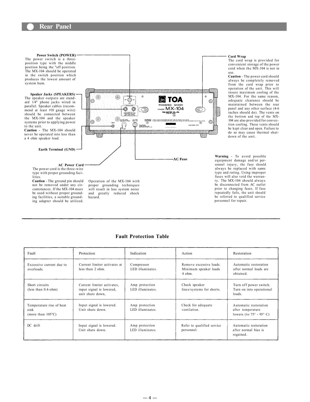
Power Switch (POWER)
The power switch is a three- position type with the middle position being the "off position.
The
in the switch position which produces the lowest amount of system hum.
Speaker Jacks (SPEAKERS)
The speaker outputs are stand- ard 1/4" phone jacks wired in parallel. Speaker cables (recom- mend at least #18 gauge wire) should be connected between the
systems prior to applying power to the unit.
Caution - The
never be operated into less than
a 4 ohm speaker load.
Earth Terminal (GND)
AC Power Cord
The power cord is the
type with proper grounding faci-
lities.
Caution - The ground pin should
not be removed under any cir- cumstances. If the
Operation of the
will result in less system noise
and greatly reduced shock hazard.
Cord Wrap
The cord wrap is provided for convenient storage of the power cord when the
Caution - The power cord should
always be completely removed from the cord wrap prior to operation of the unit. This will insure maximum cooling of the
104are also provided for convec- tion cooling. These vents should be kept clear and open. Failure to do so may cause thermal shut- down of the unit.
Warning - To avoid possible
equipment damage and/or per- sonnel injury, the fuse should always be replaced with same type and rating. Using improper
fuses will also void the warran-
ty. The
Fault Protection Table
Fault | Protection | Indication | Action | Restoration |
Excessive current due to | Current limiter activates at | Compressor | Remove excessive loads. | Automatic restoration |
overloads. | less than 2 ohm. | LED illuminates. | Minimum speaker loads | after normal loads are |
|
|
| 4 ohm. | obtained. |
Short circuits | Current limiter activates, | Amp protection | Check speaker | Turn off power switch. |
(less than | input signal is lowered, | LED illuminates. | lines/systems for shorts. | Turn on into operational |
| unit shuts down, |
|
| loads. |
Temperature rise of heat | Input signal is lowered. | Amp protection | Check for adequate | Automatic restoration |
sink | Unit shuts down. | LED illuminates. | ventilation. | after temperature |
(more than 105°C) |
|
|
| lowers (to 75° - 95° C) |
DC drift | Input signal is lowered. | Amp protection | Refer to qualified service | Automatic restoration |
| Unit shuts down. | LED illuminates. | personnel. | after normal bias is |
|
|
|
| regained. |
— 4 —