SETUP – SD-M1401 DVD-ROM
The following steps must be performed to properly install your drive:
•Set DVD-ROM Drive Jumper Settings: SCSI ID, Parity, Termination, 512/2K, Power
•Connect Audio Cable
•Attach SCSI Interface Cable
•Attach Power Cable
•Daisy-Chaining SCSI Drives (if applicable)
•Mount Drive
Jumper Settings
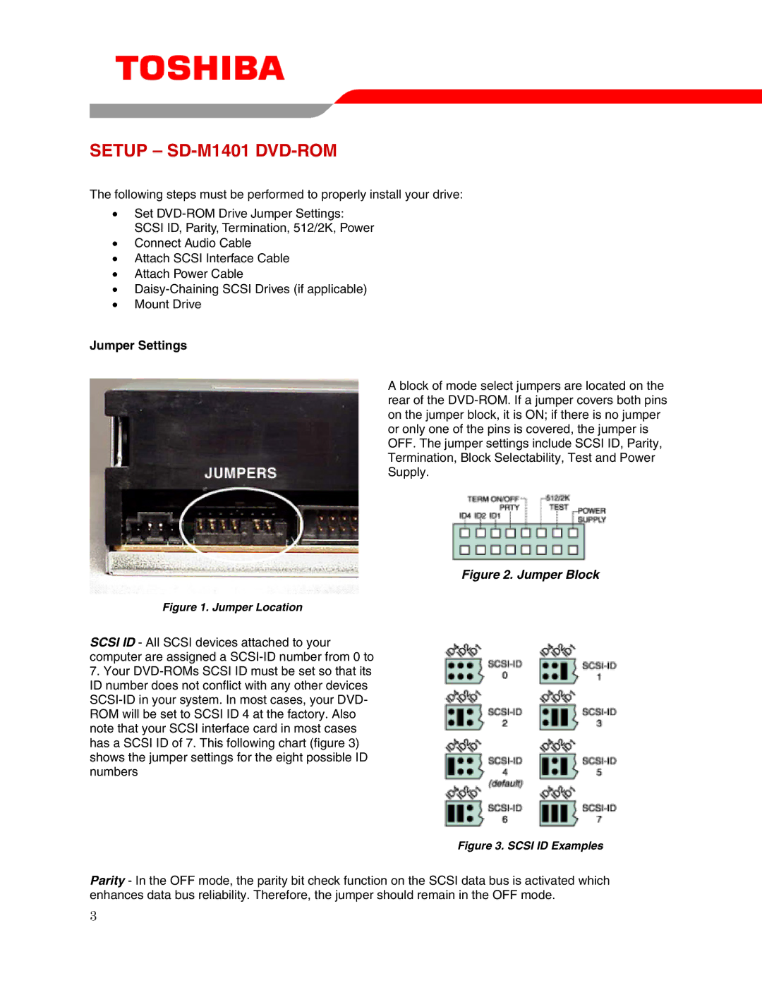
Figure 1. Jumper Location
SCSI ID - All SCSI devices attached to your computer are assigned a SCSI-ID number from 0 to
7.Your DVD-ROMs SCSI ID must be set so that its ID number does not conflict with any other devices SCSI-ID in your system. In most cases, your DVD- ROM will be set to SCSI ID 4 at the factory. Also note that your SCSI interface card in most cases has a SCSI ID of 7. This following chart (figure 3) shows the jumper settings for the eight possible ID numbers
A block of mode select jumpers are located on the rear of the DVD-ROM. If a jumper covers both pins on the jumper block, it is ON; if there is no jumper or only one of the pins is covered, the jumper is OFF. The jumper settings include SCSI ID, Parity, Termination, Block Selectability, Test and Power Supply.
Figure 2. Jumper Block
Figure 3. SCSI ID Examples
Parity - In the OFF mode, the parity bit check function on the SCSI data bus is activated which enhances data bus reliability. Therefore, the jumper should remain in the OFF mode.
3