♦Gateway Modes
There are two communications ports on the Gateway, labeled PLC1 and PLC2. Each port can be configured for either RS232 or RS485 operation. Gateway can communicate through either the
♦Gateway Setup
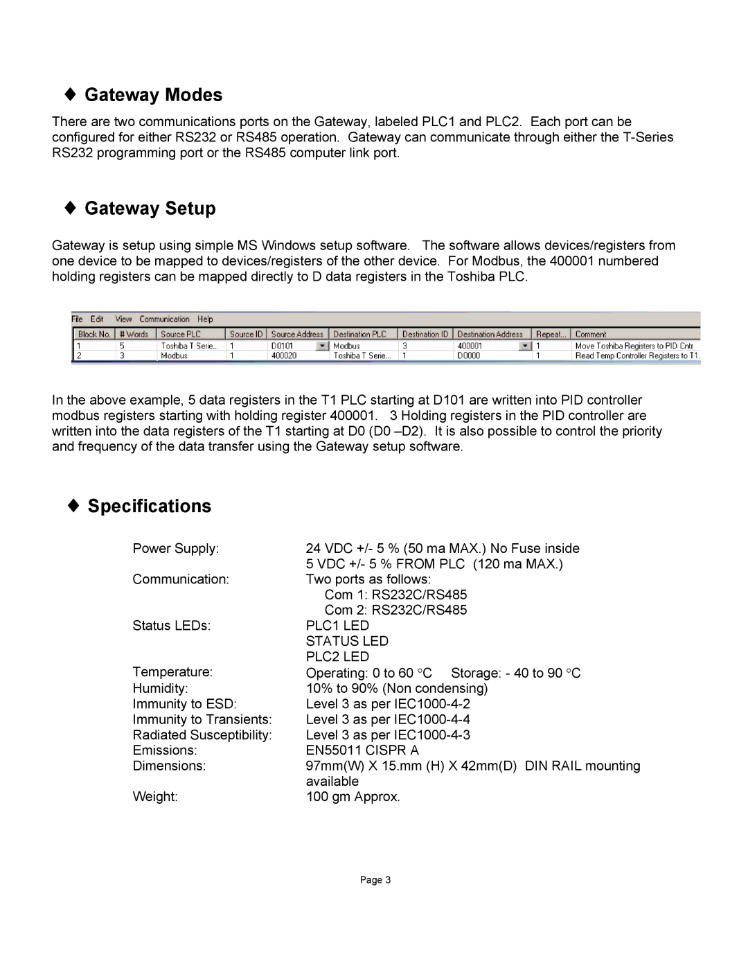
Gateway is setup using simple MS Windows setup software. The software allows devices/registers from one device to be mapped to devices/registers of the other device. For Modbus, the 400001 numbered holding registers can be mapped directly to D data registers in the Toshiba PLC.
In the above example, 5 data registers in the T1 PLC starting at D101 are written into PID controller modbus registers starting with holding register 400001. 3 Holding registers in the PID controller are written into the data registers of the T1 starting at D0 (D0
♦ Specifications
Power Supply: | 24 VDC +/- 5 % (50 ma MAX.) No Fuse inside |
| 5 VDC +/- 5 % FROM PLC (120 ma MAX.) |
Communication: | Two ports as follows: |
| Com 1: RS232C/RS485 |
| Com 2: RS232C/RS485 |
Status LEDs: | PLC1 LED |
| STATUS LED |
Temperature: | PLC2 LED |
Operating: 0 to 60 °C Storage: - 40 to 90 °C | |
Humidity: | 10% to 90% (Non condensing) |
Immunity to ESD: | Level 3 as per |
Immunity to Transients: | Level 3 as per |
Radiated Susceptibility: | Level 3 as per |
Emissions: | EN55011 CISPR A |
Dimensions: | 97mm(W) X 15.mm (H) X 42mm(D) DIN RAIL mounting |
| available |
Weight: | 100 gm Approx. |
Page 3