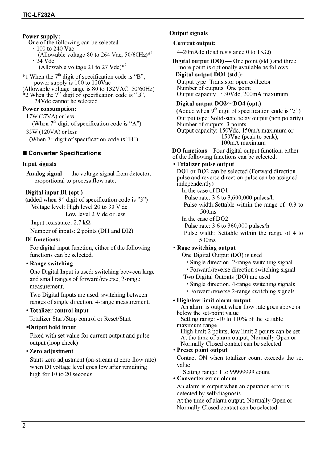
TIC-LF232A specifications
The Toshiba TIC-LF232A is an advanced inverter air conditioning system designed to optimize energy efficiency while delivering outstanding cooling performance. As part of Toshiba's commitment to innovation and sustainable technology, this model incorporates some of the latest advancements in climate control engineering.One of the standout features of the TIC-LF232A is its inverter technology. Unlike traditional air conditioning systems that operate on a fixed speed, the inverter technology allows the compressor to adjust its speed based on the current cooling demand. This results in significant energy savings, as the system can maintain the desired temperature more consistently while using less electricity. This feature also contributes to a quieter operation, with reduced noise levels making it suitable for residential and commercial environments alike.
The TIC-LF232A boasts a high Energy Efficiency Ratio (EER) and Seasonal Energy Efficiency Ratio (SEER), indicating its ability to deliver effective cooling with minimal energy consumption. The incorporation of eco-friendly refrigerants further emphasizes Toshiba's commitment to environmental sustainability, ensuring that users not only save on energy bills but also reduce their carbon footprint.
In addition to energy efficiency, the TIC-LF232A is equipped with a range of advanced technologies designed to enhance user comfort and convenience. The system features a smart control system that allows users to manage their air conditioning remotely via a mobile app. This feature enables users to set schedules, monitor energy usage, and adjust temperature settings from anywhere, providing maximum flexibility and control.
Another key characteristic of the TIC-LF232A is its multi-zone capability. The system can simultaneously provide cooling to multiple rooms or areas, allowing for customized comfort in different spaces. This is particularly beneficial for larger homes or commercial buildings where individualized climate control is valuable.
The TIC-LF232A also prioritizes air quality with its integrated filtration system. It includes advanced filters that enhance indoor air quality by capturing dust, allergens, and other particles, promoting a healthier living environment.
Overall, the Toshiba TIC-LF232A stands out as a cutting-edge air conditioning solution that combines superior energy efficiency, innovative technologies, and user-centric features, making it a top choice for those seeking reliable and effective climate control solutions.

