26.Check for miswiring, loose screws. Grease the fixing bolts for the cover, gas- ket, and tap holes in the scanner chassis. Attach the cover.
When the de-icer is installed
1)Before beginning any work on the scanner unit, turn off the breaker for the de- icer line at the main switchboard to remove the power (100 VAC, 1ø) to the de- icer. (Turning off the power to the display unit has no effect.)
2)The neck of the scanner unit becomes VERY HOT when the
2.3Changing AC Power Specification of Display Unit
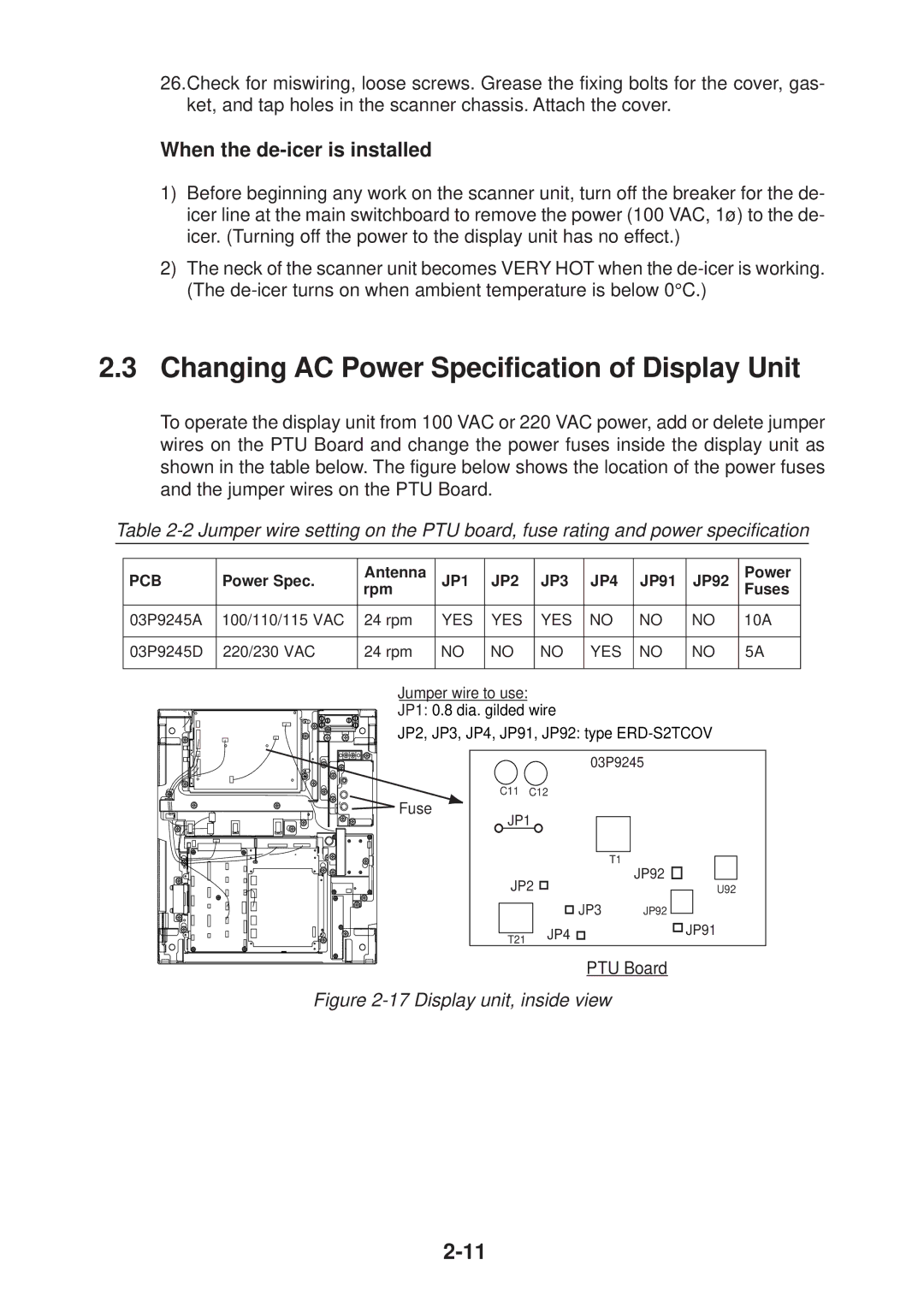
To operate the display unit from 100 VAC or 220 VAC power, add or delete jumper wires on the PTU Board and change the power fuses inside the display unit as shown in the table below. The figure below shows the location of the power fuses and the jumper wires on the PTU Board.
Table
PCB | Power Spec. | Antenna | JP1 | JP2 | JP3 | JP4 | JP91 | JP92 | Power | |
rpm | Fuses | |||||||||
|
|
|
|
|
|
|
| |||
|
|
|
|
|
|
|
|
|
| |
03P9245A | 100/110/115 VAC | 24 rpm | YES | YES | YES | NO | NO | NO | 10A | |
|
|
|
|
|
|
|
|
|
| |
03P9245D | 220/230 VAC | 24 rpm | NO | NO | NO | YES | NO | NO | 5A | |
|
|
|
|
|
|
|
|
|
|
Jumper wire to use:
JP1: 0.8 dia. gilded wire
JP2, JP3, JP4, JP91, JP92: type
![]()
![]()
![]()
![]()
![]()
![]() Fuse
Fuse
03P9245
C11 C12
JP1
|
|
| T1 |
| |||||
JP2 |
| JP92 |
|
|
|
| |||
JP3 | JP92 |
|
|
|
|
| U92 | ||
|
|
|
|
| |||||
|
|
|
| ||||||
|
|
| |||||||
|
| JP4 |
|
|
|
| JP91 | ||
|
|
|
|
|
| ||||
T21 |
|
|
|
| |||||
|
|
|
|
|
|
| |||
|
|
|
|
|
|
|
| ||
PTU Board