9.Remove the sheath of each conductor by 6 mm. Fix
10.Tighten the clamping gland.
11. Seal the cable gland with putty.
12.Connect the conductors to terminal board
Fabricating signal cable S03-74
13.At the signal cable gland on the scanner unit, unfasten the clamping gland and remove gasket and flat washers.
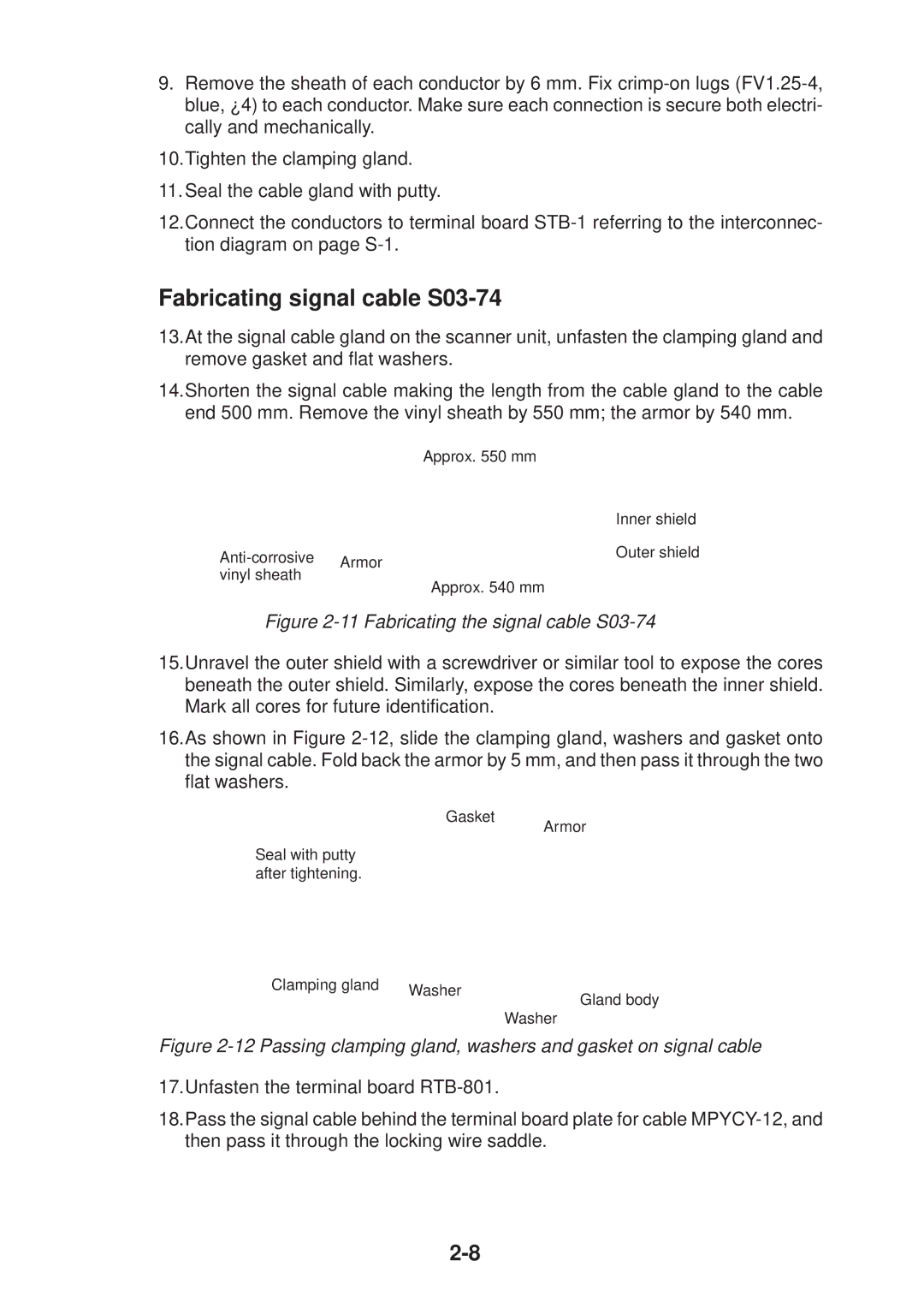
14.Shorten the signal cable making the length from the cable gland to the cable end 500 mm. Remove the vinyl sheath by 550 mm; the armor by 540 mm.
|
| Approx. 550 mm |
|
| |
|
|
|
|
| Inner shield |
Armor |
|
|
| Outer shield | |
|
|
|
| ||
vinyl sheath |
|
|
|
| |
|
|
|
|
| |
|
|
| Approx. 540 mm |
| |
Figure 2-11 Fabricating the signal cable S03-74
15.Unravel the outer shield with a screwdriver or similar tool to expose the cores beneath the outer shield. Similarly, expose the cores beneath the inner shield. Mark all cores for future identification.
16.As shown in Figure
Gasket
Seal with putty after tightening.
Armor
Clamping gland |
|
|
| |
|
|
| ||
Washer | Gland body | |||
| ||||
|
|
| ||
|
|
| Washer | |
Figure 2-12 Passing clamping gland, washers and gasket on signal cable
17.Unfasten the terminal board
18.Pass the signal cable behind the terminal board plate for cable