1.2 Display Unit
Before mounting the display unit
If Gyro Converter
Mounting considerations
When selecting a mounting location, keep in mind the following points:
•Select a location where the display unit can be viewed and operated conve- niently and where the screen can be viewed while facing towards the bow.
•Locate the unit out of direct sunlight and away from heat sources because of heat that can build up inside the cabinet.
•Locate the equipment away from places subject to water splash and rain.
•The display unit is very heavy. Be sure the mounting location is strong enough to support the weight of the unit under the continued vibration which is normally experienced on the ship. If necessary reinforce the mounting location.
•Determine the mounting location considering the length of the signal cable be- tween the scanner unit and the display unit and the power cable between the display unit and Power Supply Unit
•Leave sufficient space on the sides and rear of the unit to facilitate mainte- nance. Also, leave a foot or so of “service loop” in cables behind the unit so it can be pulled forward for servicing or easy removal of connectors.
•A magnetic compass will be affected if placed too close to the display unit. Observe the following compass safe distances to prevent deviation of a mag- netic compass: Standard compass, 1.70 m, Steering compass, 0.90 m.
Mounting procedure
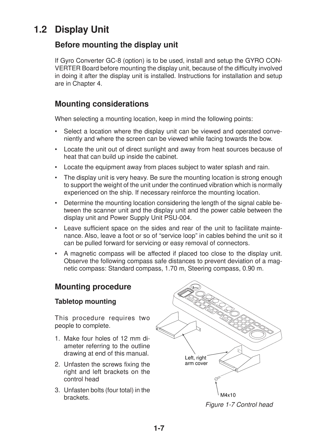
Tabletop mounting
This procedure requires two people to complete.
1.Make four holes of 12 mm di- ameter referring to the outline drawing at end of this manual.
2.Unfasten the screws fixing the right and left brackets on the control head
3.Unfasten bolts (four total) in the brackets.
Left, right arm cover
M4x10