10.Fasten the front panel of the display pedestal.
11.Fasten the ground wire to the location shown in Figure
4.4 Performance Monitor PM-50
Necessary parts: PM-50 and OP03-150 (Code no. 008-485-490)
Name | Type | Qty | Code No. |
|
|
|
|
PM Board | 03P9225 | 1 |
|
|
|
|
|
Pan Head Screw | M3x8 C2700W | 3 | |
|
|
|
|
Connector Assy. | 2 | ||
|
|
|
|
1.Lift the monitor. See Chapter 1 for instructions.
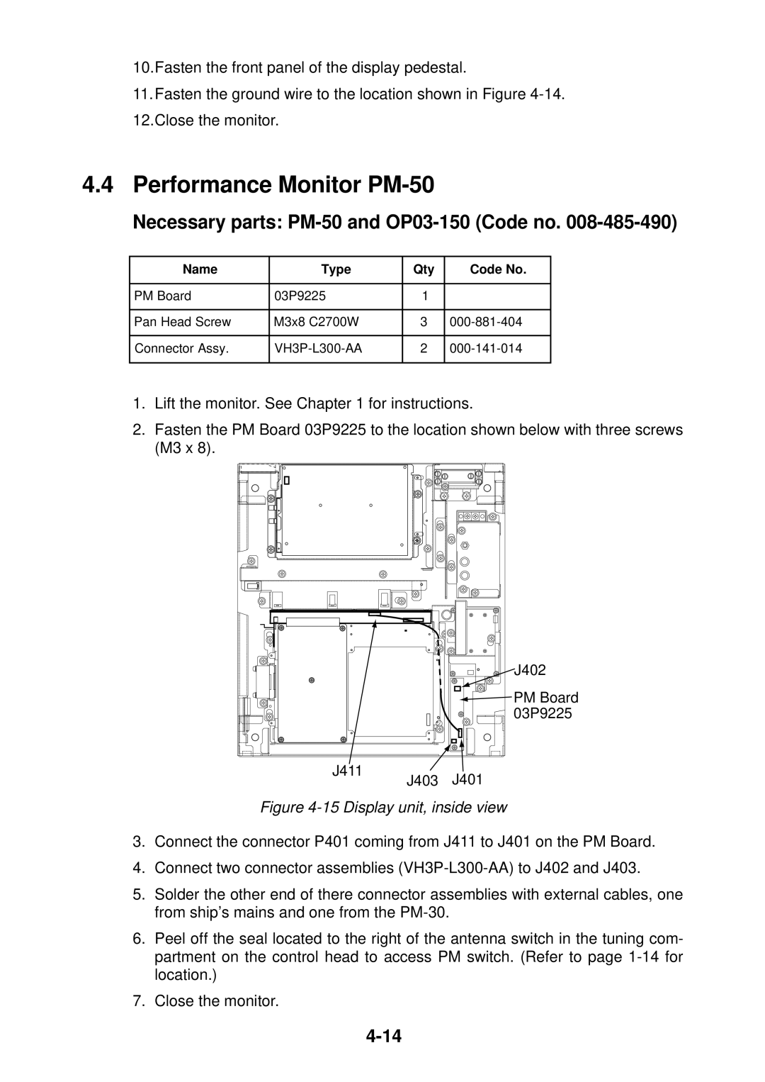
2.Fasten the PM Board 03P9225 to the location shown below with three screws (M3 x 8).
J411
J402 |
![]() PM Board 03P9225
PM Board 03P9225
J403 J401
Figure 4-15 Display unit, inside view
3.Connect the connector P401 coming from J411 to J401 on the PM Board.
4.Connect two connector assemblies
5.Solder the other end of there connector assemblies with external cables, one from ship’s mains and one from the
6.Peel off the seal located to the right of the antenna switch in the tuning com- partment on the control head to access PM switch. (Refer to page
7.Close the monitor.