< btUt
MaxiLife Test Sequence and Error Messages
Rz® h6™
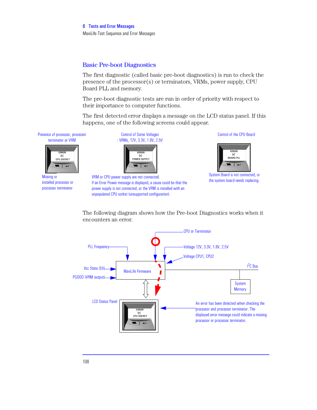
The first diagnostic (called basic
The
The first detected error displays a message on the LCD status panel. If this happens, one of the following screens could appear.
Presence of processor, processor | Control of Some Voltages | Control of the CPU Board |
terminator or VRM | : VRMs, 12V, 3.3V, 1.8V, 2.5V |
|
M‘‘W‘
KXc aWKSMb
Missing or![]()
![]() installed processor or processor terminator
installed processor or processor terminator
M‘‘W‘ | M‘‘W‘ |
XWeM‘ acXXTg | JWI‘L XTT |
|
VRM or CPU power supply are not connected. | System Board is not connected, or | |
the system board needs replacing. | ||
If an Error Power message is displayed, a cause could be that the | ||
| ||
power supply is not connected, or the VRM is installed with an |
| |
unpopulated CPU socket (unsupported configuration). |
|
The following diagram shows how the
CPU or Terminator
PLL Frequency
Vcc State (5V)![]()
![]() PGOOD (VRM output)
PGOOD (VRM output)![]()
![]()
MaxiLife Firmware
Voltage 12V, 3.3V, 1.8V, 2.5V
Voltage CPU1, CPU2
I2C Bus
System
Memory
LCD Status Panel
|
|
|
|
|
|
| An error has been detected when checking the |
|
|
|
|
|
|
| processor and processor terminator. The |
| M‘‘W‘ |
|
|
| |||
| KXc aWKSMb |
|
|
| displayed error message could indicate a missing | ||
|
|
|
|
|
|
| processor or processor terminator. |
|
|
|
|
|
|
| |
|
|
|
|
|
|
|
|
