7 at• J½p
Accessory Card Slots
Q®®z
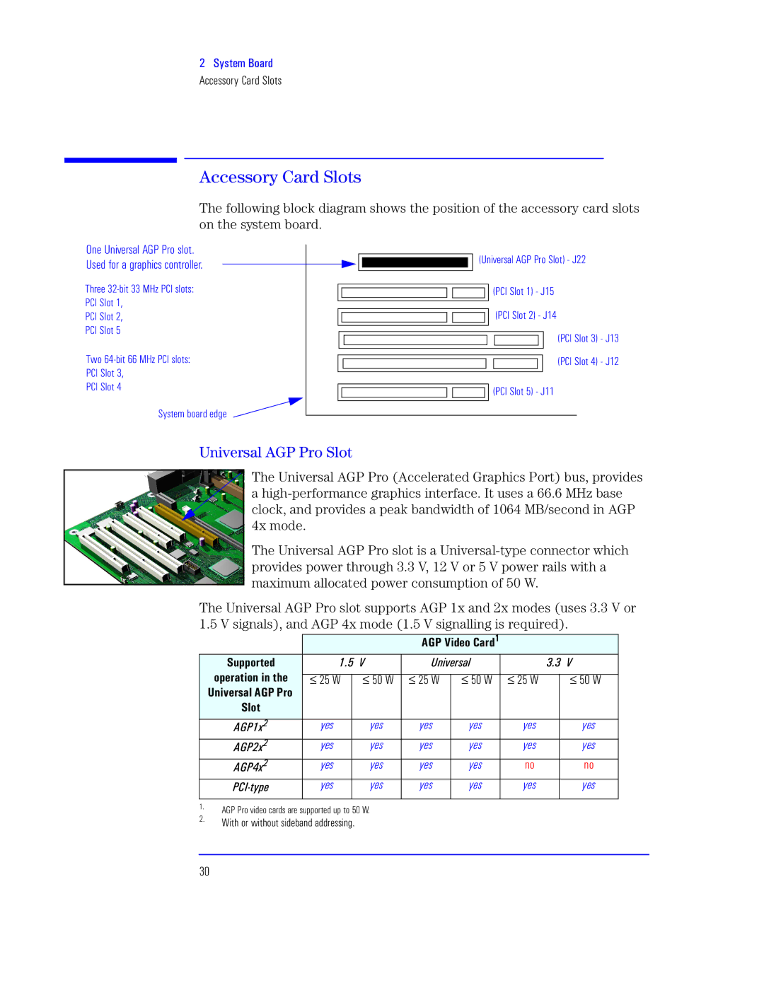
The following block diagram shows the position of the accessory card slots on the system board.
One Universal AGP Pro slot. Used for a graphics controller.
Three
PCI Slot 2,
PCI Slot 5
Two
PCI Slot 3,
PCI Slot 4
System board edge
(Universal AGP Pro Slot) - J22 |
(PCI Slot 1) - J15 |
(PCI Slot 2) - J14 |
(PCI Slot 3) - J13 |
(PCI Slot 4) - J12 |
(PCI Slot 5) - J11 |
nz QWh h
The Universal AGP Pro (Accelerated Graphics Port) bus, provides a
The Universal AGP Pro slot is a
The Universal AGP Pro slot supports AGP 1x and 2x modes (uses 3.3 V or 1.5 V signals), and AGP 4x mode (1.5 V signalling is required).
|
|
| JPZ dxstLp | 6 |
|
| |
|
|
|
|
|
|
|
|
ats | 84C n | m |
|
| A4A n |
| |
wt |
|
|
|
|
|
|
|
≤ 25 W | ≤ 50 W | ≤ 25 W | ≤ 50 W |
| ≤ 25 W | ≤ 50 W | |
cxPZ Z |
|
|
|
|
|
|
|
a® |
|
|
|
|
|
|
|
|
|
|
|
|
|
|
|
OVg8 : |
|
|
|
|
|
|
|
OVg: : |
|
|
|
|
|
|
|
OVgB : |
|
|
|
|
| no | no |
gRX3 |
|
|
|
|
|
|
|
|
|
|
|
|
|
|
|
1.AGP Pro video cards are supported up to 50 W.
2.With or without sideband addressing.
30