7 a• J½p
PCI 64-bit Hub
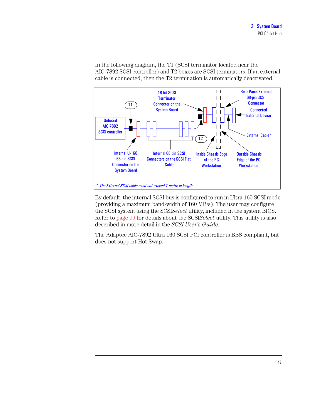
In the following diagram, the T1 (SCSI terminator located near the
| 6<2qx aKaQ |
| ‘tp Xp”t“ M”p“ |
| btx”p½ |
| <>2¼x” aKaQ |
b6 | K½””tr½” t |
| K½””tr½ |
| at• J½ps |
| K½””trts |
W”q½ps |
|
| M“ Ltxrt |
|
|
| |
IQK2=>A7 |
|
|
|
aKaQ r½”½““t |
|
| Mtp“ Kpq“t/ |
|
| b7 | |
|
|
| |
Q”t”p“ c26<5 | Q”t“ <>2¼x” aKaQ | Q”xst Kwpsvt | Wst Kwp |
<>2¼x” aKaQ | K½””tr ½” wt aKaQ N“p | ½u wt XK | Msvt ½u t XK |
K½””tr ½” | Kpq“t | e½” | e½” |
a½ps |
|
|
|
/ l kRkX 8 |
|
|
|
By default, the internal SCSI bus is configured to run in Ultra 160 SCSI mode (providing a maximum
the SCSI system using the SCSIl | utility, included in the system BIOS. | |
Refer to page 99 for details about the SCSIl | utility. This utility is also | |
described in more detail in the lTla User’s Guide.
The Adaptec
47
