= K½””tr½zt
Rear Panel Socket Pin Layouts
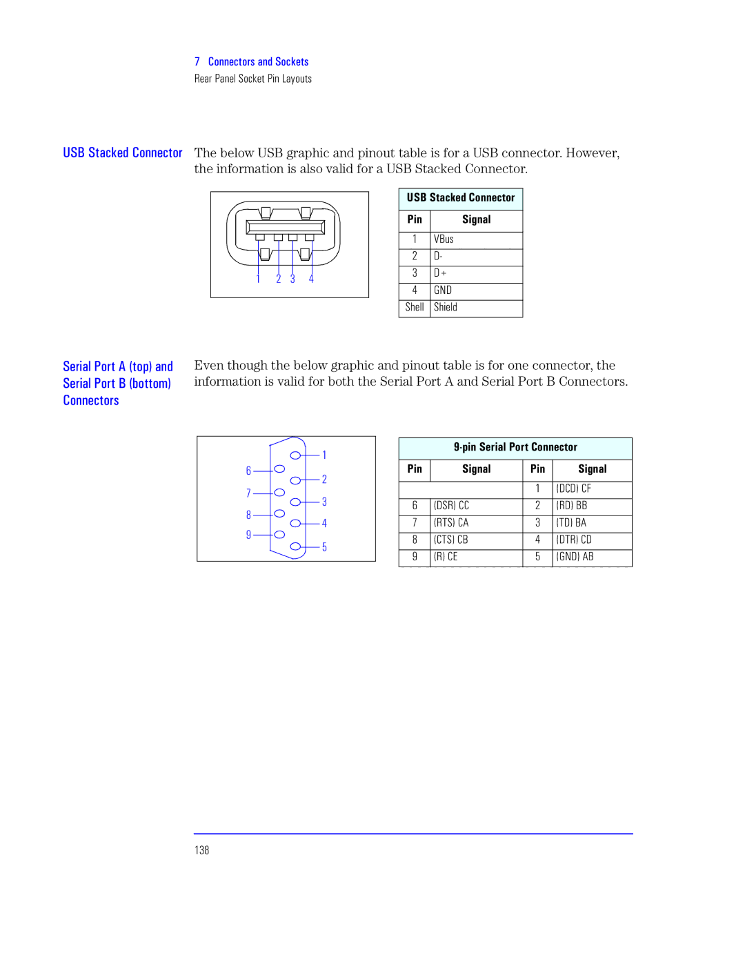
caJ arzts K½””tr The below USB graphic and pinout table is for a USB connector. However, the information is also valid for a USB Stacked Connector.
1 2 3 4
caK aprzts Ltr
Zx | axv |
1VBus
2D-
3D+
4 GND
Shell Shield
at½ I -½¼. p”s atp“ X½•. K½””tr½
Even though the below graphic and pinout table is for one connector, the information is valid for both the Serial Port A and Serial Port B Connectors.
6
7
8
9
1
2
3
4
5
B2atp® Z Lr
Zx | axv | Zx |
| axvp® |
|
|
|
|
|
|
|
| 1 | (DCD) CF |
|
|
|
|
|
6 | (DSR) CC |
| 2 | (RD) BB |
|
|
|
|
|
7 | (RTS) CA |
| 3 | (TD) BA |
|
|
|
|
|
8 | (CTS) CB |
| 4 | (DTR) CD |
|
|
|
|
|
9 | (R) CE |
| 5 | (GND) AB |
|
|
|
|
|