7 a• J½p
System Board Switches
l®
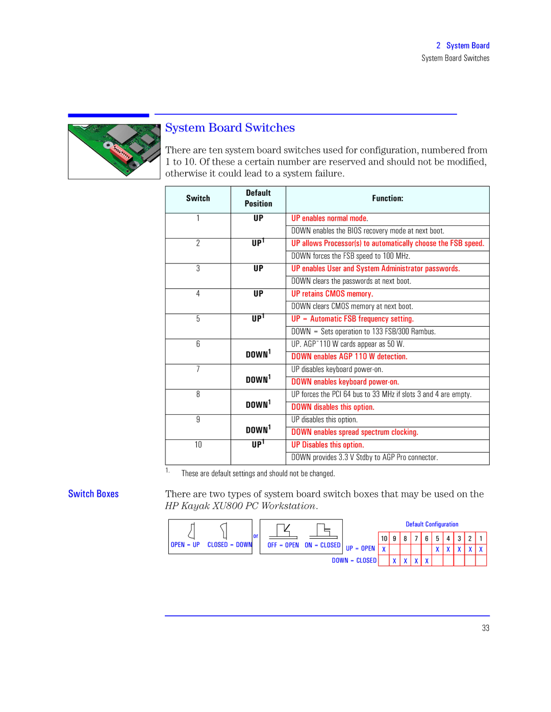
There are ten system board switches used for configuration, numbered from 1 to 10. Of these a certain number are reserved and should not be modified, otherwise it could lead to a system failure.
axw | Mtup® | O | |
Z | |||
|
| ||
|
|
| |
1 | cZ | cX t”pq“t”½•p“ •½st . | |
|
|
| |
|
| DOWN enables the BIOS recovery mode at next boot. | |
2 | cZ6 | cX p““½ X½rt. ½ pxrp““w½½ NaJ ts3 | |
|
| DOWN forces the FSB speed to 100 MHz. | |
|
|
| |
3 | cZ | cX t”pq“t c p”s a• Is•x”x½¼ps3 | |
|
|
| |
|
| DOWN clears the passwords at next boot. | |
|
|
| |
4 | cZ | cX t”•t•½ | |
|
|
| |
|
| DOWN clears CMOS memory at next boot. | |
5 | cZ6 | cX E I½•pr NaJ u”r”v3 | |
|
| DOWN = Sets operation to 133 FSB/300 Rambus. | |
|
|
| |
6 | MYeW6 | UP. AGP¨110 W cards appear as 50 W. | |
|
| ||
| LWeV t”pq“t IOX 665 e sttrx½”3 | ||
|
|
| |
7 | MYeW6 | UP disables keyboard | |
|
| ||
| LWeV t”pq“t zt½½”3 | ||
8 | MYeW6 | UP forces the PCI 64 bus to 33 MHz if slots 3 and 4 are empty. | |
|
| ||
| LWeV sxt ½¼½”3 | ||
9 | MYeW6 | UP disables this option. | |
|
| ||
| LWeV t”pq“t ps rr“½rzx”v3 | ||
10 | cZ6 | cX Lxt x½”3 | |
|
| DOWN provides 3.3 V Stdby to AGP Pro connector. | |
|
|
|
1.These are default settings and should not be changed.
arw J½ | There are two types of system board switch boxes that may be used on the | |
| Yh c“qnG<< hT p | . |
WXMV E cX KTWaML E LWeV
½
|
|
|
|
|
|
|
|
|
|
|
|
|
|
|
| Ltup K½”uxvpx½” |
|
|
|
| ||||
|
|
|
|
|
|
|
|
|
|
|
|
|
|
|
|
|
|
|
| |||||
|
|
|
|
|
|
|
|
|
|
|
|
|
|
|
|
|
|
|
|
|
|
|
|
|
|
|
|
|
|
|
|
|
|
|
|
|
|
| 65 | A | > | = | < | : |
| 9 | 8 | 7 | 6 |
WNN E WXMV WV E KTWaML | cX E WXMV |
| ||||||||||||||||||||||
|
|
|
|
|
|
|
|
|
|
| ||||||||||||||
f |
|
|
|
| f |
| f | f | f | f | ||||||||||||||
|
|
|
|
|
|
|
|
|
| LWeV E KTWaML |
| f | f | f | f |
|
|
|
|
|
| |||
33
