7 at• J½p
The Input/Output Controller Hub (82801AA)
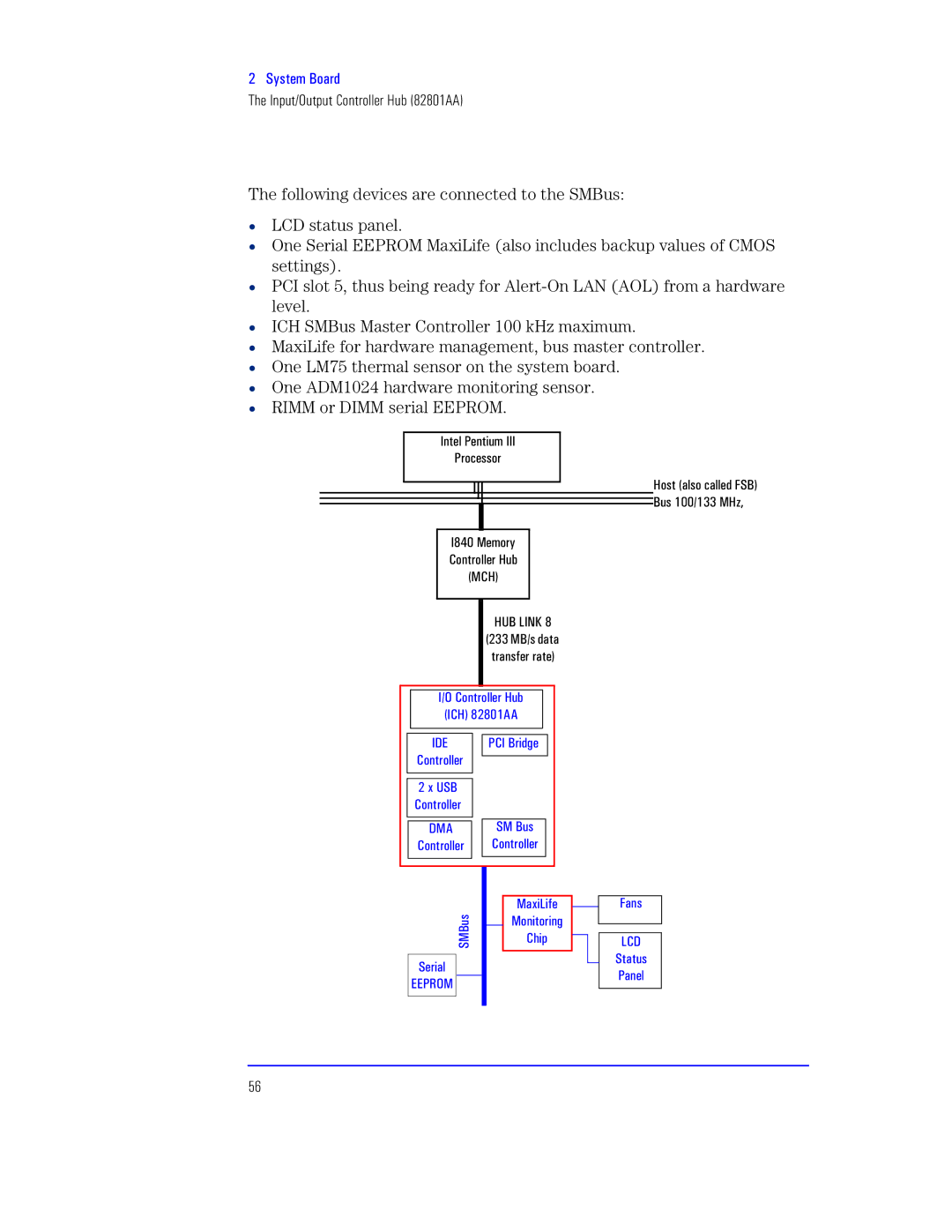
The following devices are connected to the SMBus:
•LCD status panel.
•One Serial EEPROM MaxiLife (also includes backup values of CMOS settings).
•PCI slot 5, thus being ready for
•ICH SMBus Master Controller 100 kHz maximum.
•MaxiLife for hardware management, bus master controller.
•One LM75 thermal sensor on the system board.
•One ADM1024 hardware monitoring sensor.
•RIMM or DIMM serial EEPROM.
Q”• QQQ
Xrt
Q>95 Ut•½
K½”““t Pq
PcJ TQVS >
P½“ rp““ts NaJ.
J6554688 UP
Q4W K½”½““t Pq
| QLM |
|
| XKQ Jvt |
|
|
| ||
| K½”½““t |
|
|
|
|
|
|
|
|
|
|
|
|
|
|
|
|
| |
|
|
|
|
|
|
|
|
|
|
|
|
|
|
|
|
|
|
|
|
| 7 caJ |
|
|
|
|
|
|
|
|
| K½”““t |
|
|
|
|
|
|
|
|
|
|
|
|
|
|
|
|
|
|
|
|
|
|
|
|
|
|
|
|
| LUI |
|
| aU J |
|
|
|
| |
| K½”““t |
|
| K½”““t |
|
|
|
| |
|
|
|
|
|
|
|
|
|
|
|
|
|
|
|
|
|
|
|
|
|
|
|
|
|
|
|
|
|
|
|
|
|
|
|
|
|
|
|
|
|
|
|
|
| Up |
|
| ||
|
|
|
|
|
|
| |||
|
| aUJ |
| U½”xx”v |
|
| |||
|
|
| Kwx¼ |
|
| ||||
|
|
|
|
|
|
| |||
|
|
|
|
|
|
|
|
|
|
|
|
|
|
|
|
|
|
|
|
| at“ |
|
|
|
|
|
|
|
|
|
|
|
|
|
|
|
|
| |
| MMX‘WU |
|
|
|
|
|
|
|
|
|
|
|
|
|
|
|
|
|
|
|
|
|
|
|
|
|
|
|
|
Np”
TKL a Xp”t“