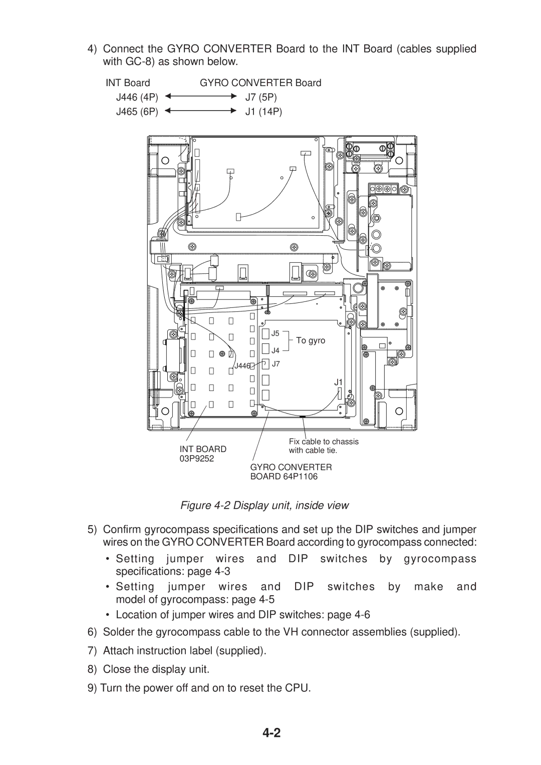
4)Connect the GYRO CONVERTER Board to the INT Board (cables supplied with
INT Board | GYRO CONVERTER Board | |
J446 (4P) | J7 | (5P) |
J465 (6P) | J1 | (14P) |
J5
To gyro
J4
J446![]()
![]()
![]() J7
J7
J1
Fix cable to chassis
INT BOARDwith cable tie. 03P9252
GYRO CONVERTER BOARD 64P1106
Figure 4-2 Display unit, inside view
5)Confirm gyrocompass specifications and set up the DIP switches and jumper wires on the GYRO CONVERTER Board according to gyrocompass connected:
•Setting jumper wires and DIP switches by gyrocompass specifications: page
• Setting jumper wires and DIP switches by make and model of gyrocompass: page
•Location of jumper wires and DIP switches: page
6)Solder the gyrocompass cable to the VH connector assemblies (supplied).
7)Attach instruction label (supplied).
8)Close the display unit.
9)Turn the power off and on to reset the CPU.