20.Route the signal cable beneath the lower left side of the terminal board fixing plate for the
75 mm
Coaxial cable
50 mm
Fold back the conductor as illustrated below.
45 mm |
| Inner core |
|
![]() (Red, ∅3)
(Red, ∅3)
Conductor
6 mm | |
| |
(Red, ∅3) |
|
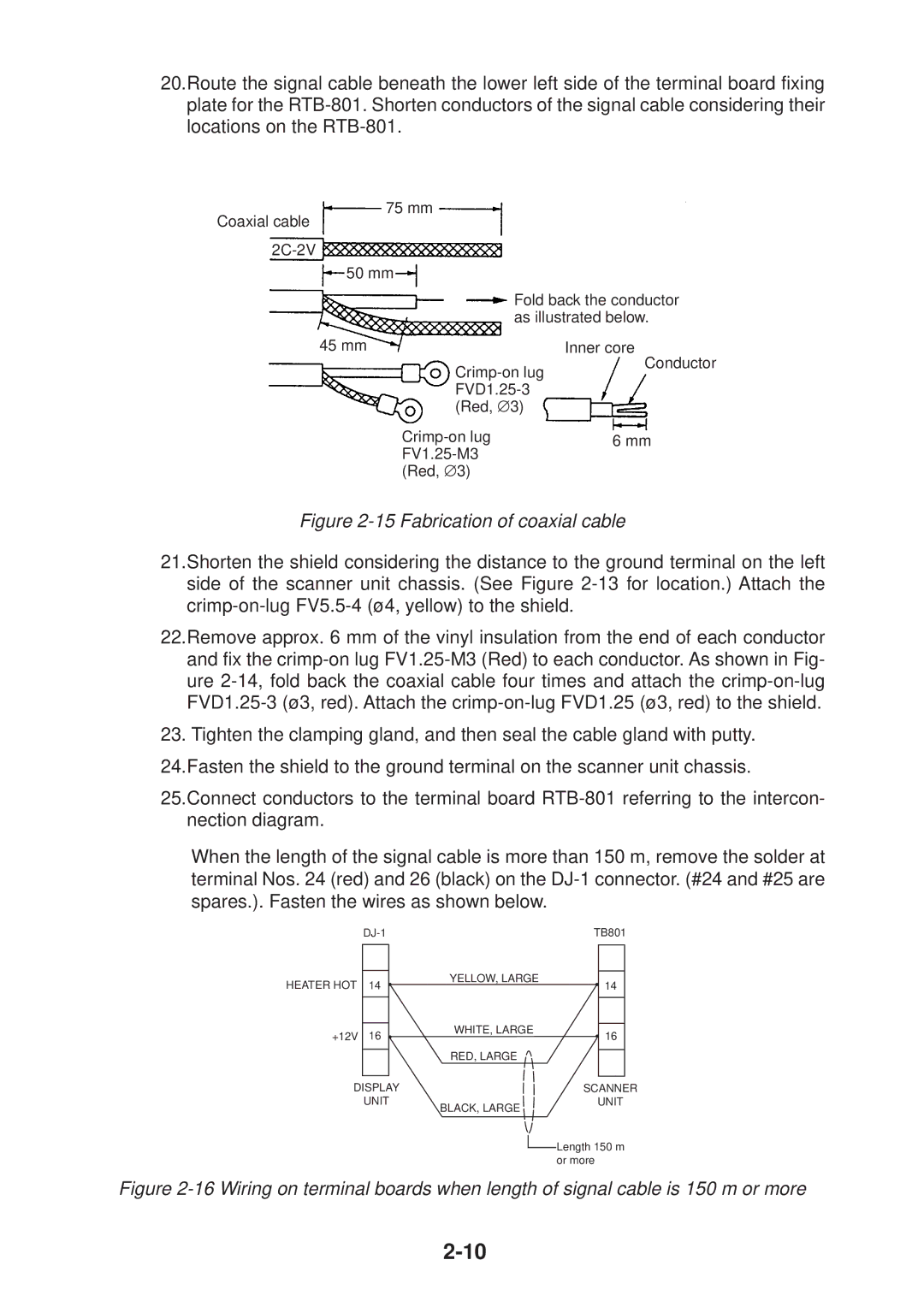
Figure 2-15 Fabrication of coaxial cable
21.Shorten the shield considering the distance to the ground terminal on the left side of the scanner unit chassis. (See Figure
22.Remove approx. 6 mm of the vinyl insulation from the end of each conductor and fix the
23. Tighten the clamping gland, and then seal the cable gland with putty.
24.Fasten the shield to the ground terminal on the scanner unit chassis.
25.Connect conductors to the terminal board
When the length of the signal cable is more than 150 m, remove the solder at terminal Nos. 24 (red) and 26 (black) on the
|
| TB801 | |
HEATER HOT | 14 | YELLOW, LARGE | 14 |
| |||
+12V | 16 | WHITE, LARGE | 16 |
| |||
|
| RED, LARGE |
|
DISPLAY |
| SCANNER | |
| UNIT | BLACK, LARGE | UNIT |
|
|
| |
|
|
| Length 150 m |
|
|
| or more |