Appendix A
Slide Kit Connector
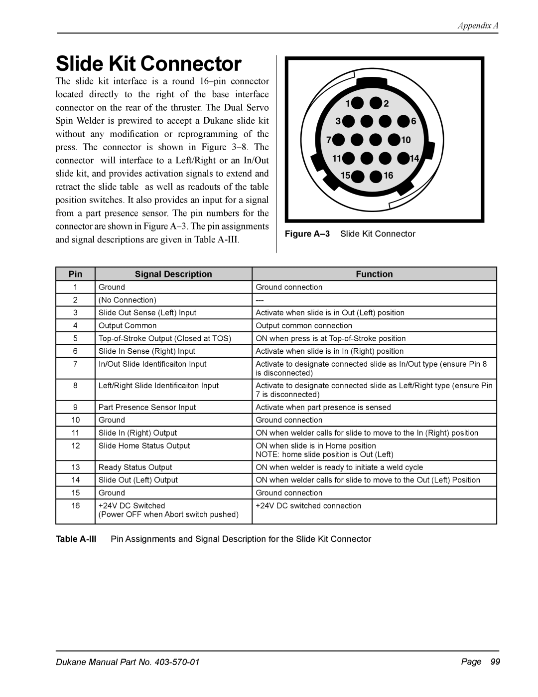
The slide kit interface is a round
1![]()
![]() 2
2
3![]()
![]()
![]()
![]() 6
6
7![]()
![]()
![]()
![]() 10
10
11![]()
![]()
![]()
![]() 14
14
15![]()
![]() 16
16
Figure A–3 Slide Kit Connector
Pin | Signal Description | Function |
1 | Ground | Ground connection |
|
|
|
2 | (No Connection) | |
|
|
|
3 | Slide Out Sense (Left) Input | Activate when slide is in Out (Left) position |
|
|
|
4 | Output Common | Output common connection |
|
|
|
5 | ON when press is at | |
|
|
|
6 | Slide In Sense (Right) Input | Activate when slide is in In (Right) position |
|
|
|
7 | In/Out Slide Identificaiton Input | Activate to designate connected slide as In/Out type (ensure Pin 8 |
|
| is disconnected) |
|
|
|
8 | Left/Right Slide Identificaiton Input | Activate to designate connected slide as Left/Right type (ensure Pin |
|
| 7 is disconnected) |
|
|
|
9 | Part Presence Sensor Input | Activate when part presence is sensed |
|
|
|
10 | Ground | Ground connection |
|
|
|
11 | Slide In (Right) Output | ON when welder calls for slide to move to the In (Right) position |
|
|
|
12 | Slide Home Status Output | ON when slide is in Home position |
|
| NOTE: home slide position is Out (Left) |
|
|
|
13 | Ready Status Output | ON when welder is ready to initiate a weld cycle |
|
|
|
14 | Slide Out (Left) Output | ON when welder calls for slide to move to the Out (Left) Position |
|
|
|
15 | Ground | Ground connection |
|
|
|
16 | +24V DC Switched | +24V DC switched connection |
| (Power OFF when Abort switch pushed) |
|
|
|
|
Table
Dukane Manual Part No. | Page 99 |