Dual Servo Spin Welder User’s Manual
Securing to Work Bench
Bench Capacity
The Dual Servo Spin Welder weighs approximately 400 lbs. (182 kg). It should be attached to a table or bench capable of supporting 650 lbs. (295 kg) to accommodate the additional force imposed by the vertical movement of the motor and slide during the spin welding operation.
Use mechanical means such as a forklift or hoist to place the servo spin welder on its work bench. There are two 3/4 inch lifting eyes located at the top of the column (see Figure
Leveling
We recommend that the Dual Servo Spin Welder be leveled to within one degree. This can be accomplished using a carpenter’s level. One degree corresponds to approximately
Mounting Holes
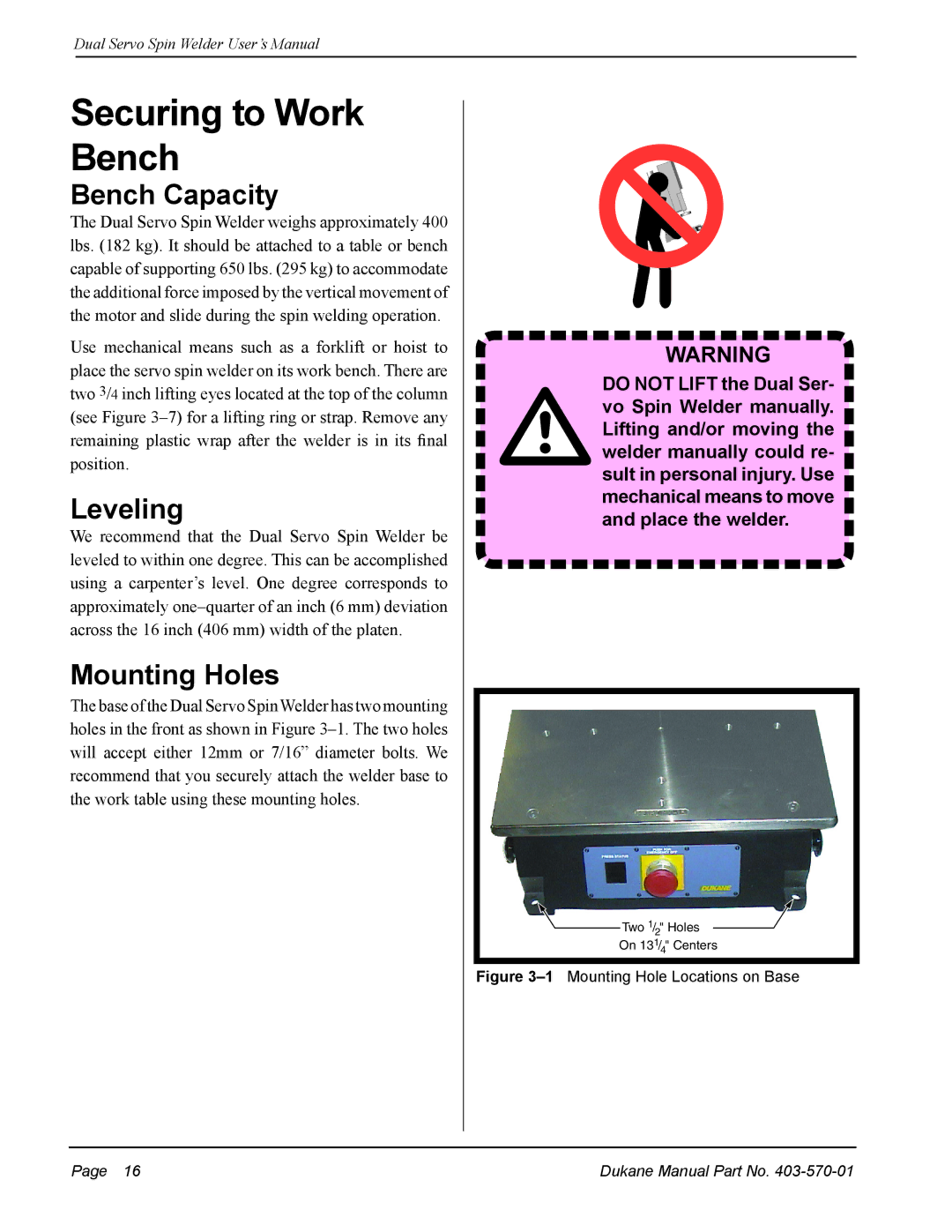
The base of the Dual Servo SpinWelder has two mounting holes in the front as shown in Figure
WARNING
DO NOT LIFT the Dual Ser- vo Spin Welder manually. Lifting and/or moving the welder manually could re- sult in personal injury. Use mechanical means to move and place the welder.
Two 1/2" Holes
On 131/4" Centers
Figure 3–1 Mounting Hole Locations on Base
Page 16 | Dukane Manual Part No. |