Section 5 - Touch Screen Menus
Torque Trigger Option
This option specifies a torque level to sense when the
upper and lower parts make contact. Prior to contact, the motor is spinning the tool in the air using a very low amount torque. At contact, there is an increase in the torque required to maintain a constant angular velocity,
at which point the weld is considered to start (i.e. the weld timer and counter are started). Note that the welder begins to sense the torque after reaching the TRIGGER
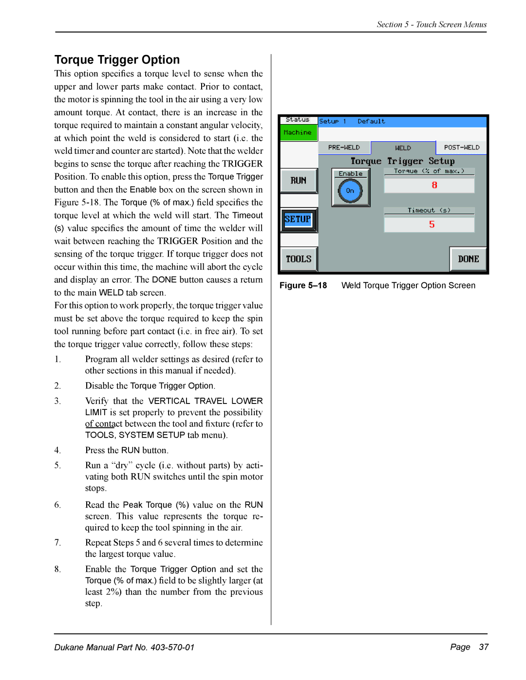
Position. To enable this option, press the Torque Trigger button and then the Enable box on the screen shown in
Figure 5-18. The Torque (% of max..) field specifies the
torque level at which the weld will start. The Timeout
(s)value specifies the amount of time the welder will wait between reaching the TRIGGER Position and the sensing of the torque trigger. If torque trigger does not occur within this time, the machine will abort the cycle and display an error. The DONE button causes a return to the main WELD tab screen.
For this option to work properly, the torque trigger value must be set above the torque required to keep the spin tool running before part contact (i.e. in free air). To set the torque trigger value correctly, follow these steps:
1.Program all welder settings as desired (refer to other sections in this manual if needed).
2.Disable the Torque Trigger Option.
3.Verify that the VERTICAL TRAVEL LOWER LIMIT is set properly to prevent the possibility of contact between the tool and fixture (refer to
TOOLS, SYSTEM SETUP tab menu).
4.Press the RUN button.
5.Run a “dry” cycle (i.e. without parts) by acti- vating both RUN switches until the spin motor stops.
6.Read the Peak Torque (%) value on the RUN screen. This value represents the torque re- quired to keep the tool spinning in the air.
7.Repeat Steps 5 and 6 several times to determine the largest torque value.
8.Enable the Torque Trigger Option and set the
Torque (% of max..) field to be slightly larger (at least 2%) than the number from the previous step.
Figure 5–18 Weld Torque Trigger Option Screen
Dukane Manual Part No. | Page 37 |
