Dukane 403-570-01 user manual Head Height Adjustment, Control Connectors, Base Interface Connector

Models: 403-570-01

1 118
Download 118 pages 61.57 Kb
Page 25
Image 25

Section 3 - Unpacking and Setup

Head Height

Adjustment

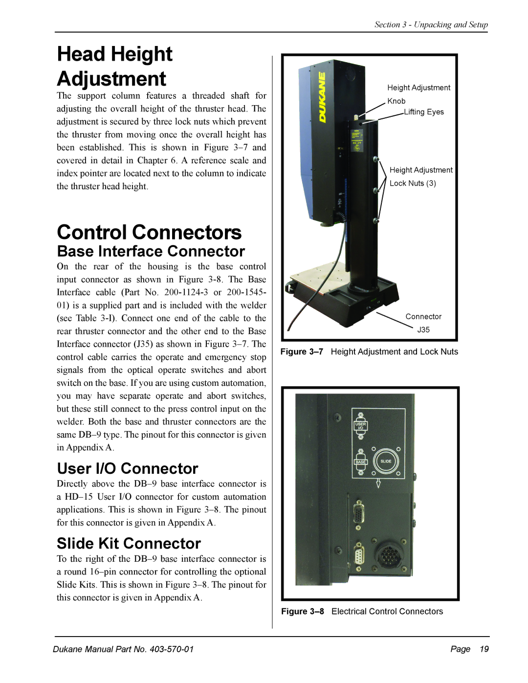
The support column features a threaded shaft for adjusting the overall height of the thruster head. The adjustment is secured by three lock nuts which prevent the thruster from moving once the overall height has been established. This is shown in Figure 3–7 and covered in detail in Chapter 6. A reference scale and index pointer are located next to the column to indicate the thruster head height.

Control Connectors

Base Interface Connector

On the rear of the housing is the base control input connector as shown in Figure 3-8. The Base Interface cable (Part No. 200-1124-3 or 200-1545-

01)is a supplied part and is included with the welder (see Table 3-I). Connect one end of the cable to the rear thruster connector and the other end to the Base

Interface connector (J35) as shown in Figure 3–7. The control cable carries the operate and emergency stop signals from the optical operate switches and abort switch on the base. If you are using custom automation, you may have separate operate and abort switches, but these still connect to the press control input on the welder. Both the base and thruster connectors are the same DB–9 type. The pinout for this connector is given in Appendix A.

User I/O Connector

Directly above the DB–9 base interface connector is a HD–15 User I/O connector for custom automation applications. This is shown in Figure 3–8. The pinout for this connector is given in Appendix A.

Slide Kit Connector

To the right of the DB–9 base interface connector is a round 16–pin connector for controlling the optional Slide Kits. This is shown in Figure 3–8. The pinout for this connector is given in Appendix A.

Height Adjustment

Knob

Lifting Eyes

Height Adjustment

Lock Nuts (3)

Connector

J35

Figure 3–7Height Adjustment and Lock Nuts

Figure 3–8Electrical Control Connectors

Dukane Manual Part No. 403-570-01

Page  19

Page 25
Image 25
Dukane 403-570-01 user manual Head Height Adjustment, Control Connectors, Base Interface Connector, User I/O Connector